MAX7219 8×8 LED Dot Matrix Display with Arduino.
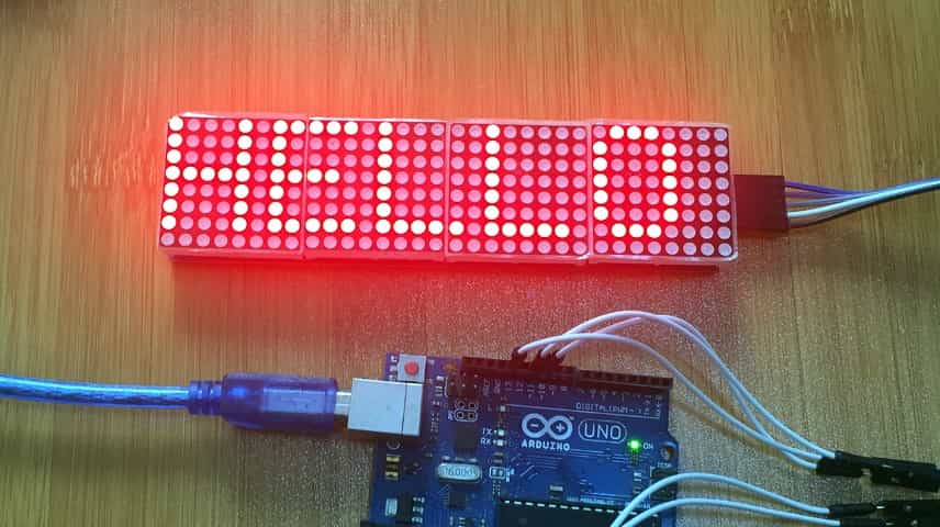
LED matrices have many applications in today’s world mainly in displaying text, flashing marquee and images on billboards, digital clocks and in many more other areas. This tutorial is a detailed explanation of how these matrices work and how they can be interfaced with Arduino.
What is LED matrix?
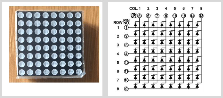
This is an array of LEDs arranged in rows and columns and can be used to display numbers, letters, and shapes. They come is various sizes but the most common one is the 8×8 LED matrix, that is, 64 LEDs arranged in 8 rows and 8 columns.
The LEDs are wired either as common-anode or common-cathode. In both cases, all of the LEDs’ anodes in a row or column are wired together and all of the LEDs’ cathodes in a column or row are also wired together.
How does the LED matrix work?
It’s not possible to turn multiple LEDs in different rows and columns ON and keep them ON at the same time. To create the visual effect where all designated LEDs appear to be on at the same time, a vision persistence method is used.
Our eyes remember a flash of light for approximately 20ms, so when you continuously flash a light at a rate of or faster than 20ms, then it appears that the light never goes off.
Using this concept, the microcontroller turns ON the required LEDs in a row or column, one row or one column after the other, cycling through all rows or columns to turn on the required LEDs, at a rate greater than 20ms which tricks human eyes into seeing the designated LEDs appear to be ON at the same time!
Using the MAX7219 IC to control 8×8 LED matrix.
In order to control the 8×8 LED matrix directly with a microcontroller, you need to connect each row and each column to a digital pin, which means you would need 16 I/O pins. This is way too many pins for controlling a single device.
To solve this problem, we can use the MAX7219 IC to drive the 64 LEDs using only 3 wires to interface it to a microcontroller. In addition, you can even daisy chain multiple MAX7219 chips for bigger displays without a need for extra I/O pins.
MAX7219 Pin configuration
The MAX7219 is a 24-pin IC designed as a serial input common-cathode display driver used to interface microcontrollers to 7-segment numeric LED displays of up to 8 digits, bar-graph displays or 64 individual LEDs. In this case we are using it to control 8×8 LED matrix.
Below is the diagram and description for each pin of the MAX7219 IC.
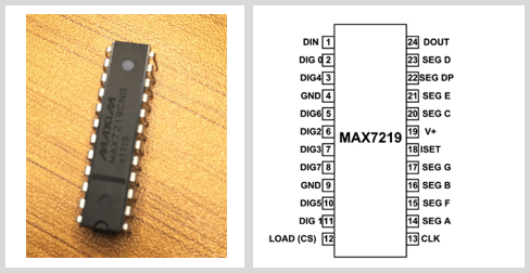
- DIG0 – DIG7: Common cathode of display segments, that is, all the eight segments for Digit0 to Digit7 have a common ground.
- SEG A – SEG G : Shared segment terminal of all eight digits.
Function pins
- DIN – Serial Data Input Pin
- LOAD(CS) – Chip Select or Data shift pin
- CLK – Clock Pin
- DOUT – Pin used to Connect Second chip serially
- ISET – current output adjust pin
Connecting the MAX7219 IC to 8×8 LED Matrix.
The figure below shows the circuit of how the MAX7219 is connected to 8×8 LED matrix and the way the various components are arranged on commercial breakout boards.
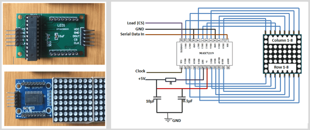
The MAX7219 pins labelled SEG A~F are connected to the row pins of the LED matrix and the pins DIG 0~7 to the columns respectively.
NOTE: There is a resistor between the 5V and the MAX7219 pin 18. Since this IC is a constant- current LED driver, the value of the resistor is used to set the current flow to the LEDs which is important in controlling the brightness of the LEDs.
In case you are designing your own matrix LED with MAX7219 IC, in order to choose the right resistor, you need to know the voltage and forward current for your LED matrix, then match the value with the ones in the Rset vs Segment Current and LED forward voltage table from the MAX7219 datasheet as shown below;
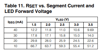
For example, if you have a 2V 20 mA LED, your resistor value will be 28kΩ.
Hardware overview.
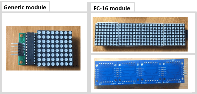
There are a number of pre-wired LED matrices with MAX7219 on the market available in different color styles and dimensions. However, for most beginners’ electronics projects, the generic and FC-I6 LED matrix modules shown below are commonly used.
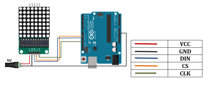
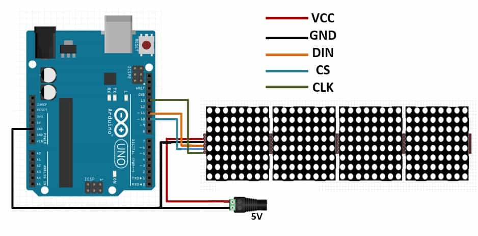
Connecting the MAX7219 LED matrix with Arduino.
The MAX7219 driver communicates with the Arduino through SPI (Serial Peripheral Interface) where the Arduino acts as the master device and the LED matrix will be the slave.
To achieve this, you only need three connections:
- Data line (DIN) – is the MOSI (Master Out Slave In) for SPI communication
- Serial Clock (CLK) – The clock pulses which synchronize data transmission generated by the master.
- Chip Select (CS) – The pin on each device that the master can use to enable and disable specific devices.
SPI communication can either be hardware or software based. Hardware SPI is faster but only works with specific SPI pins for the given Arduino board for example for Arduino UNO the SPI pins are 10, 11 and 13 for Chip Select (CS), Data (DIN) and Serial Clock (CLK) respectively.
When using software SPI, you can use any digital pin of the Arduino but you need to declare these pins in the code.
One of the major advantages of the MAX7219 chip is that it enables us to daisy-chain multiple 8×8 LED matrices to create a larger display that still uses only 3 pins for SPI communication. To daisy-chain the matrices, connect the DOUT of the first display to the DIN of the next display and the other pins, that is, VCC, GND, CLK and CS will all be shared between the displays.
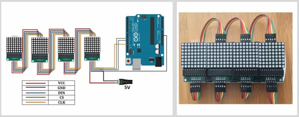
The FC-I6 module already has the connections for daisy-chaining the 8×8 led matrices made on the breakout board therefore you only need to connect the VCC, GND, DIN, CLK and CS output pins to the Arduino as shown below.
Power Considerations
The maximum power that the Arduino Uno can safely deliver when powered from USB is around 400 mA at 5 V. LED matrix displays have a fairly high current draw and can use up to 1A if the brightness is set to maximum.
Always use an external power supply for the display. Never connect more than four led matrices directly to the microcontroller and always keep the brightness less than 50% to avoid destroying the microcontroller’s voltage regulator.
Controlling the 8×8 LED matrix using MAX7219 and Arduino.
There are two ways of using the MAX7219 chip to control LED matrix. One is using procedural programming to send the data bit by bit and the second way is to use previously written libraries for this chip.
Using libraries is easiest way to get the required result because there is no need of worrying about detailed programming. You only need to input the required data to be displayed on the LED matrix. I will give a demonstration of how to use both methods in the examples below;
Using procedural programming
The example below is a demonstration of the code we can use to display a character on an 8×8 LED display.
// set pin definition
int DIN_pin = 2;
int LOAD_pin = 3;
int CLOCK_pin = 4;

// MAX7219 register address
byte max7219_REG_noop = 0x00;
byte max7219_REG_digit0 = 0x01;
byte max7219_REG_digit1 = 0x02;
byte max7219_REG_digit2 = 0x03;
byte max7219_REG_digit3 = 0x04;
byte max7219_REG_digit4 = 0x05;
byte max7219_REG_digit5 = 0x06;
byte max7219_REG_digit6 = 0x07;
byte max7219_REG_digit7 = 0x08;
byte max7219_REG_decodeMode = 0x09;
byte max7219_REG_intensity = 0x0a;
byte max7219_REG_scanLimit = 0x0b;
byte max7219_REG_shutdown = 0x0c;
byte max7219_REG_displayTest = 0x0f;

void SPI_SendByte(byte data) {// Emulate SPI interface
 byte i = 8;
 byte mask;
 while(i > 0) {
mask = 0x01 << (i - 1);// create masking bit,
 // starting from Left
digitalWrite( CLOCK_pin, LOW);// Set clock synchronization
 // pin to LOW
 if (data & mask){// Compare masking bit to corresponding bit
 digitalWrite(DIN_pin, HIGH);// If corresponding bit is 1,
 // output HIGH to DIN
 }
 else{
 digitalWrite(DIN_pin, LOW);// If corresponding bit is 0,
 // output LOW to DIN
 }
digitalWrite(CLOCK_pin, HIGH);// Set clock synchronization
 // pin to HIGH
 --i;// Move to next bit
 }
}

// Control one MAX7219 module
void MAX7219_1Unit(byte reg_addr, byte reg_data) {

 // Before sending data set the LOAD pin to LOW
 digitalWrite(LOAD_pin, LOW);
 // First, send the register address
 SPI_SendByte(reg_addr);
 // Next, send the data
 SPI_SendByte(reg_data);
 // After transmission, set the LOAD pin to HIGH
digitalWrite(LOAD_pin,HIGH);
}

byte matrixData_8X8[8] = { // Matrix pattern

 B00000000,// row 1, top to bottom
 B01110110,
 B10001001,
 B10001001,
 B10001001,
 B10001001,
 B01110110,
 B00000000

};

void Draw (byte *LED_matrix) // Display data to LED matrix
{
 MAX7219_1Unit(1, LED_matrix[0]);
 MAX7219_1Unit(2, LED_matrix[1]);
 MAX7219_1Unit(3, LED_matrix[2]);
 MAX7219_1Unit(4, LED_matrix[3]);
 MAX7219_1Unit(5, LED_matrix[4]);
 MAX7219_1Unit(6, LED_matrix[5]);
 MAX7219_1Unit(7, LED_matrix[6]);
 MAX7219_1Unit(8, LED_matrix[7]);
}

void setup ( ) {
 pinMode(DIN_pin, OUTPUT);
 pinMode(CLOCK_pin, OUTPUT);
 pinMode(LOAD_pin, OUTPUT);

 digitalWrite(CLOCK_pin, HIGH);

 // Initialize MAX7219 registers
 MAX7219_1Unit(max7219_REG_scanLimit, 0x07);// set to scan all row
 // Disable decoding
 MAX7219_1Unit(max7219_REG_decodeMode, 0x00);
 // Not shutdown mode
 MAX7219_1Unit(max7219_REG_shutdown, 0x01);
 // Not test mode
 MAX7219_1Unit(max7219_REG_displayTest, 0x00);

 for(int i=1; i<=8; i++) {// Set all LED intensity to low
 MAX7219_1Unit(i,0);
 }

 // Set LED intensity range: 0x00 ~ 0x0f
 MAX7219_1Unit(max7219_REG_intensity, 0x0a);

 delay(1000);
}

void loop () {
 Draw(matrixData_8X8);
 delay(500);
}
First, we need to send serial data to the chip bit by bit through the DIN pin by setting the clock for each sent bit. The chip stores the serial data in its registers until all data is received.
Once all data is received then we shift this serial data to the output by enabling CS pin which will light up the corresponding LEDs to display the result.
SPI_SendByte(byte data) function is used to emulate SPI interface, sending one byte of data.
MAX7219_1Unit(byte reg_addr, byte reg_data) function is used to write 16-bit data to the register of a single MAX7219 LED matrix module.
When data is ready to be sent via the DIN data line, the CLK line is set to HIGH and then LOW and the LOAD signal line is set to LOW prior to data transmission and then set to HIGH after data transmission is completed.
The matrixData_8x8[] byte array is used to store display data, 0 to turn LED off and 1 to turn LED on.
In the Draw() function, to draw image on the 8×8 LED matrix, it calls the MAX7219_1Unit() and turn the LEDs to on or off, one row at a time, to control 8 row of LEDs.
In the setup() function, in addition to initializing the I/O pin mode, it also initializes registers on the MAX7219 chip. Registers on the MAX7219 chip must be initialized in order to function properly.
In the loop() function, the Draw() function is called continuously, to display data to the LED matrix, with 500ms delay between each call.
Displaying static and scrolling text on LED matrix using Libraries.
As you can observe from the example given above, writing the code for running the LED matrix from scratch is rather challenging and may not be advisable for people who want to use the matrix but are not good with programming.
This is where the use of already written libraries comes in handy!
There are a number of libraries for running text, characters and animations on LED matrices and I’ll look at some of the common ones.
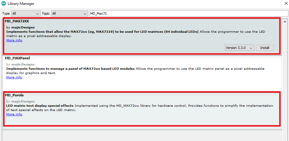
Using the MD_MAX72XX.h and MD_Parola.h libaries.
These libraries are used together where the MD-MAX72XX library contains the hardware functionalities of the LED matrix and the MD_Parola library is used for crating the various text animations and effects.
You will also need to include the SPI library, which comes pre-installed in the Arduino IDE and is used for the Serial Peripheral Interface communication between the display and the Arduino.
Using these two libraries you can be able to display text and graphics on the same display, scroll text, make user defined fonts and other functions.
You can install these libraries from the Arduino IDE Library Manager. Go to the Sketch > Include Library > Manage Libraries.
Code for displaying static text messages on the LED matrix.
#include <MD_Parola.h>
#include <MD_MAX72xx.h>
#include <SPI.h>

// Uncomment according to your hardware type
#define HARDWARE_TYPE MD_MAX72XX::FC16_HW
//#define HARDWARE_TYPE MD_MAX72XX::GENERIC_HW

// Defining size, and output pins
#define MAX_DEVICES 4
#define CS_PIN 10

// Create a new instance of the MD_Parola class with hardware SPI connection
MD_Parola myDisplay = MD_Parola(HARDWARE_TYPE, CS_PIN, MAX_DEVICES);

void setup() {
  // Intialize the object
  myDisplay.begin();

  // Set the intensity (brightness) of the display (0-15)
  myDisplay.setIntensity(0);

  // Clear the display
  myDisplay.displayClear();

}

void loop() {
  myDisplay.setTextAlignment(PA_LEFT);
  myDisplay.print("Left");
  delay(2000);

  myDisplay.setTextAlignment(PA_CENTER);
  myDisplay.print("HELLO");
  delay(4000);

  myDisplay.setTextAlignment(PA_RIGHT);
  myDisplay.print("Right");
  delay(2000);

  myDisplay.setTextAlignment(PA_CENTER);
  myDisplay.setInvert(true);
  myDisplay.print("Invert");
  delay(2000);

  myDisplay.setInvert(false);
  myDisplay.print(1234);
  delay(2000);

}
How this code works
First include the necessary libraries, that is, MD_MAX72XX , MD_Parola and SPI libraries.
Then specify the hardware you are using by setting the HARDWARE_TYPE. If you are using the generic modules, you set it to GENERIC_HW and if you are the fc-16 type set it to FC16_HW.
Set the number of MAX7219 ICs in use for example for the FC-16 module set MAX_DEVICES to 4.
Then define which pin the CS pin of the display is connected.
By default, these libraries are set to use hardware SPI and therefore there is no need to define the data and clock pins. However, if you want to use software SPI, you need to define the data and clock output pins and pass these as parameters when setting up the display object.
Next, create a new instance of the MD_Parola class using the function MD_Parola(). This function requires three parameters, the first being the hardware type, the second the CS pin, and the third the maximum number of connected devices.
MD_Parola myDisplay = MD_Parola(HARDWARE_TYPE, CS_PIN, MAX_DEVICES);
If you are using the software SPI then you need to include the data and clock pins too.
MD_Parola P = MD_Parola(HARDWARE_TYPE, DATA_PIN, CLK_PIN, CS_PIN, MAX_DEVICES);
Functions in the setup section.
- begin() – for initializing the created object.
- setIntensity() – for setting the brightness of the display and takes values from 0 to 15.
- displayClear() – clears the display
Functions in the loop section.
- setTextAlignment() function is for aligning the printed text left, center and right using the parameters PA_LEFT, PA_CENTER, and PA_RIGHT respectively.
- print() – for displaying text on the led matrix
Code for displaying Scrolling Text
#include <MD_Parola.h>
#include <MD_MAX72xx.h>
#include <SPI.h>

// Uncomment according to your hardware type
#define HARDWARE_TYPE MD_MAX72XX::FC16_HW
//#define HARDWARE_TYPE MD_MAX72XX::GENERIC_HW

// Defining size, and output pins
#define MAX_DEVICES 4
#define CS_PIN 10

// Create a new instance of the MD_Parola class with hardware SPI connection
MD_Parola myDisplay = MD_Parola(HARDWARE_TYPE, CS_PIN, MAX_DEVICES);

void setup() {
  // Intialize the object
  myDisplay.begin();

  // Set the intensity (brightness) of the display (0-15)
  myDisplay.setIntensity(0);

  // Clear the display
  myDisplay.displayClear();

  myDisplay.displayScroll("MYTECTUTOR", PA_CENTER, PA_SCROLL_LEFT, 100);
}

void loop() {
  if (myDisplay.displayAnimate()) {
    myDisplay.displayReset();
  }
}
For scrolling text on the display, in the setup section we use the function displayScroll(pText, align, textEffect, speed) where;
- pText – is the text to be displayed.
- align – sets the alignment of text during optional pause using PA_CENTER, PA_LEFT, or PA_RIGHT.
- textEffect – specifies the scrolling effects for example PA_SCROLL_LEFT will scroll the text left.
- speed - determines the speed of the animation in milliseconds and the shorter the time, the faster the animation moves
In the loop section we use an if statement with;
- displayAnimate() function for scrolling the text and returns true when the scrolling is done.
- displayReset() function is for resetting the display to continue scrolling.
The MD_MAX72XX and MD_Parola libraries are very powerful and have vast applications that I cannot discuss all in detail in a single tutorial. You can try out the various functionalities of the Parola library using the numerous examples that have been included for practice.
Simply go to File>Examples and look for MD_Parola to try out the several examples as shown below
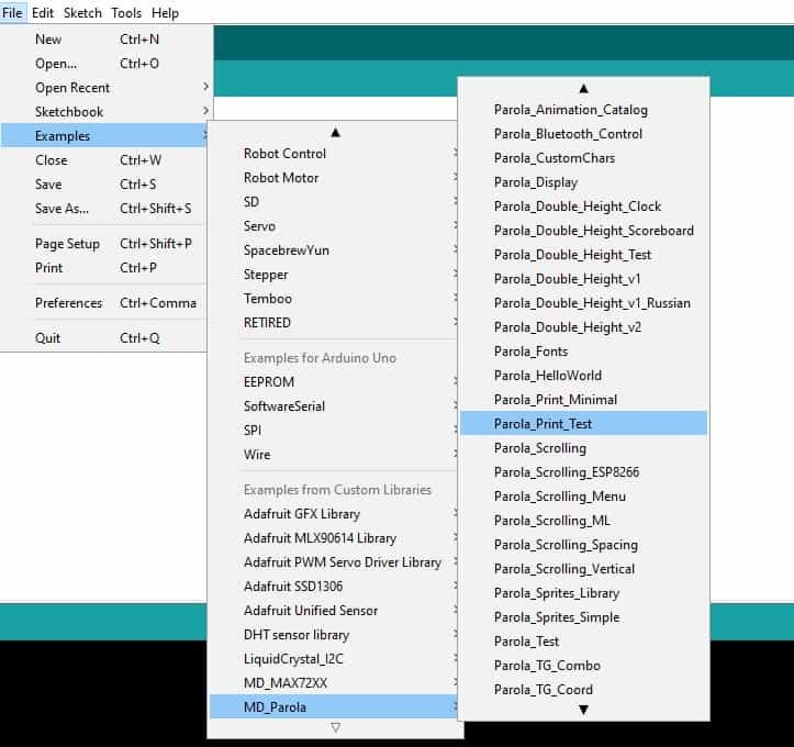
For more detailed explanation on the working of these libraries please check out the tutorials by Marco. C.
Using the Max72xxPanel.h library.
The Max722xxPanel.h library is good for displaying scrolling text messages on the Led matrix. This library works with the help of the Adafruit_GFX.h and the SPI.h libraries.
One of the challenges you may find when using this library come from the orientation of the displayed text. This is usually corrected by changing the value of the setPosition() and setRotation() functions. These functions define if and how the displays are rotated. The first display (0) is the one closest to the Arduino.
In the example below I have shown how these functions will be used for eight cascaded led matrices but the code also works fine with the four matrices. You can try changing the values and see what happens with the displayed text.
#include <SPI.h>
#include <Adafruit_GFX.h>
#include <Max72xxPanel.h>

int pinDIN = 11;   // DIN pin of MAX7219 module
int pinCLK = 13;   // CLK pin of MAX7219 module
int pinCS = 10;    // CS pin of MAX7219 module
int numberOfHorizontalDisplays=8;
int numberOfVerticalDisplays=1;

Max72xxPanel matrix= Max72xxPanel(pinCS, numberOfHorizontalDisplays, numberOfVerticalDisplays);

int scrollSpeed = 60;
int spacer = 1;
int width = 5+spacer;

void setup(){
  Serial.begin(9600);
   matrix. setIntensity ( 1 ) ;  // Adjust the brightness between 0 and 15
   matrix. setPosition ( 0 ,  0 ,  0 ) ;  // The first display is at <0, 0>
   matrix. setPosition ( 1 ,  1 ,  0 ) ;  // The second display is at <1, 0>
   matrix. setPosition ( 2 ,  2 ,  0 ) ;  // The third display is in <2, 0>
   matrix. setPosition ( 3 ,  3 ,  0 ) ;  // The fourth display is at <3, 0>
   matrix. setPosition ( 4 ,  4 ,  0 ) ;  // The fifth display is at <4, 0>
   matrix. setPosition ( 5 ,  5 ,  0 ) ;  // The sixth display is at <5, 0>
   matrix. setPosition ( 6 ,  6 ,  0 ) ;  // The seventh display is at <6, 0>
   matrix. setPosition ( 7 ,  7 ,  0 ) ;  // The eighth display is in <7, 0>
   matrix. setPosition ( 8 ,  8 ,  0 ) ;  // The ninth display is at <8, 0>
   matrix. setRotation ( 0 ,  1 ) ;     // Display position
   matrix. setRotation ( 1 ,  1 ) ;     // Display position
   matrix. setRotation ( 2 ,  1 ) ;     // Display position
   matrix. setRotation ( 3 ,  1 ) ;     // Display position
   matrix. setRotation ( 4 ,  1 ) ;     // Display position
   matrix. setRotation ( 5 ,  1 ) ;     // Display position
   matrix. setRotation ( 6 ,  1 ) ;     // Display position
   matrix. setRotation ( 7 ,  1 ) ;     // Display position
   matrix. setRotation ( 8 ,  1 ) ;     // Display position
}


  void loop(){
    String tape = " HELLO WORLD";
   long int time = millis();
   while(Serial.available()){
      string += char(Serial.read());
   }
    for(int i=0; i<width*tape.length()+matrix.width()-1-spacer; i++ ){
      matrix.fillScreen(LOW);
      int letter = i/width;
      int x = (matrix.width()-1)-i%width;
      int y = (matrix.height()-8)/2;

      while(x+width-spacer>=0 && letter>=0){
        if(letter<tape.length()){
         matrix.drawChar(x,y,tape[letter],HIGH,LOW,1);

          }
        letter--;
        x-= width;
        }
         matrix.write();
         delay(scrollSpeed);
      }
    }
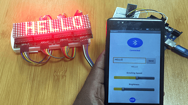
When this code is uploaded to the Arduino board, a scrolling message “HELLO WORLD” will be displayed by the led matrix.
Using the Maxmatrix.h library
This is also a common library for displaying static and scrolling text and animations on LED matrices. The example below uses this library for scrolling text message across the display.
#include <Wire.h>
#include <MaxMatrix.h>
#include <avr/pgmspace.h>
PROGMEM const unsigned char CH[] = {
  3, 8, B00000000, B00000000, B00000000, B00000000, B00000000, // space
  1, 8, B01011111, B00000000, B00000000, B00000000, B00000000, // !
  3, 8, B00000011, B00000000, B00000011, B00000000, B00000000, // "
  5, 8, B00010100, B00111110, B00010100, B00111110, B00010100, // #
  4, 8, B00100100, B01101010, B00101011, B00010010, B00000000, // $
  5, 8, B01100011, B00010011, B00001000, B01100100, B01100011, // %
  5, 8, B00110110, B01001001, B01010110, B00100000, B01010000, // &
  1, 8, B00000011, B00000000, B00000000, B00000000, B00000000, // '
  3, 8, B00011100, B00100010, B01000001, B00000000, B00000000, // (
  3, 8, B01000001, B00100010, B00011100, B00000000, B00000000, // )
  5, 8, B00101000, B00011000, B00001110, B00011000, B00101000, // *
  5, 8, B00001000, B00001000, B00111110, B00001000, B00001000, // +
  2, 8, B10110000, B01110000, B00000000, B00000000, B00000000, // ,
  4, 8, B00001000, B00001000, B00001000, B00001000, B00000000, // -
  2, 8, B01100000, B01100000, B00000000, B00000000, B00000000, // .
  4, 8, B01100000, B00011000, B00000110, B00000001, B00000000, // /
  4, 8, B00111110, B01000001, B01000001, B00111110, B00000000, // 0
  3, 8, B01000010, B01111111, B01000000, B00000000, B00000000, // 1
  4, 8, B01100010, B01010001, B01001001, B01000110, B00000000, // 2
  4, 8, B00100010, B01000001, B01001001, B00110110, B00000000, // 3
  4, 8, B00011000, B00010100, B00010010, B01111111, B00000000, // 4
  4, 8, B00100111, B01000101, B01000101, B00111001, B00000000, // 5
  4, 8, B00111110, B01001001, B01001001, B00110000, B00000000, // 6
  4, 8, B01100001, B00010001, B00001001, B00000111, B00000000, // 7
  4, 8, B00110110, B01001001, B01001001, B00110110, B00000000, // 8
  4, 8, B00000110, B01001001, B01001001, B00111110, B00000000, // 9
  2, 8, B01010000, B00000000, B00000000, B00000000, B00000000, // :
  2, 8, B10000000, B01010000, B00000000, B00000000, B00000000, // ;
  3, 8, B00010000, B00101000, B01000100, B00000000, B00000000, // <
  3, 8, B00010100, B00010100, B00010100, B00000000, B00000000, // =
  3, 8, B01000100, B00101000, B00010000, B00000000, B00000000, // >
  4, 8, B00000010, B01011001, B00001001, B00000110, B00000000, // ?
  5, 8, B00111110, B01001001, B01010101, B01011101, B00001110, // @
  4, 8, B01111110, B00010001, B00010001, B01111110, B00000000, // A
  4, 8, B01111111, B01001001, B01001001, B00110110, B00000000, // B
  4, 8, B00111110, B01000001, B01000001, B00100010, B00000000, // C
  4, 8, B01111111, B01000001, B01000001, B00111110, B00000000, // D
  4, 8, B01111111, B01001001, B01001001, B01000001, B00000000, // E
  4, 8, B01111111, B00001001, B00001001, B00000001, B00000000, // F
  4, 8, B00111110, B01000001, B01001001, B01111010, B00000000, // G
  4, 8, B01111111, B00001000, B00001000, B01111111, B00000000, // H
  3, 8, B01000001, B01111111, B01000001, B00000000, B00000000, // I
  4, 8, B00110000, B01000000, B01000001, B00111111, B00000000, // J
  4, 8, B01111111, B00001000, B00010100, B01100011, B00000000, // K
  4, 8, B01111111, B01000000, B01000000, B01000000, B00000000, // L
  5, 8, B01111111, B00000010, B00001100, B00000010, B01111111, // M
  5, 8, B01111111, B00000100, B00001000, B00010000, B01111111, // N
  4, 8, B00111110, B01000001, B01000001, B00111110, B00000000, // O
  4, 8, B01111111, B00001001, B00001001, B00000110, B00000000, // P
  4, 8, B00111110, B01000001, B01000001, B10111110, B00000000, // Q
  4, 8, B01111111, B00001001, B00001001, B01110110, B00000000, // R
  4, 8, B01000110, B01001001, B01001001, B00110010, B00000000, // S
  5, 8, B00000001, B00000001, B01111111, B00000001, B00000001, // T
  4, 8, B00111111, B01000000, B01000000, B00111111, B00000000, // U
  5, 8, B00001111, B00110000, B01000000, B00110000, B00001111, // V
  5, 8, B00111111, B01000000, B00111000, B01000000, B00111111, // W
  5, 8, B01100011, B00010100, B00001000, B00010100, B01100011, // X
  5, 8, B00000111, B00001000, B01110000, B00001000, B00000111, // Y
  4, 8, B01100001, B01010001, B01001001, B01000111, B00000000, // Z
  2, 8, B01111111, B01000001, B00000000, B00000000, B00000000, // [
  4, 8, B00000001, B00000110, B00011000, B01100000, B00000000, // \ backslash
  2, 8, B01000001, B01111111, B00000000, B00000000, B00000000, // ]
  3, 8, B00000010, B00000001, B00000010, B00000000, B00000000, // hat
  4, 8, B01000000, B01000000, B01000000, B01000000, B00000000, // _
  2, 8, B00000001, B00000010, B00000000, B00000000, B00000000, // `
  4, 8, B00100000, B01010100, B01010100, B01111000, B00000000, // a
  4, 8, B01111111, B01000100, B01000100, B00111000, B00000000, // b
  4, 8, B00111000, B01000100, B01000100, B00101000, B00000000, // c
  4, 8, B00111000, B01000100, B01000100, B01111111, B00000000, // d
  4, 8, B00111000, B01010100, B01010100, B00011000, B00000000, // e
  3, 8, B00000100, B01111110, B00000101, B00000000, B00000000, // f
  4, 8, B10011000, B10100100, B10100100, B01111000, B00000000, // g
  4, 8, B01111111, B00000100, B00000100, B01111000, B00000000, // h
  3, 8, B01000100, B01111101, B01000000, B00000000, B00000000, // i
  4, 8, B01000000, B10000000, B10000100, B01111101, B00000000, // j
  4, 8, B01111111, B00010000, B00101000, B01000100, B00000000, // k
  3, 8, B01000001, B01111111, B01000000, B00000000, B00000000, // l
  5, 8, B01111100, B00000100, B01111100, B00000100, B01111000, // m
  4, 8, B01111100, B00000100, B00000100, B01111000, B00000000, // n
  4, 8, B00111000, B01000100, B01000100, B00111000, B00000000, // o
  4, 8, B11111100, B00100100, B00100100, B00011000, B00000000, // p
  4, 8, B00011000, B00100100, B00100100, B11111100, B00000000, // q
  4, 8, B01111100, B00001000, B00000100, B00000100, B00000000, // r
  4, 8, B01001000, B01010100, B01010100, B00100100, B00000000, // s
  3, 8, B00000100, B00111111, B01000100, B00000000, B00000000, // t
  4, 8, B00111100, B01000000, B01000000, B01111100, B00000000, // u
  5, 8, B00011100, B00100000, B01000000, B00100000, B00011100, // v
  5, 8, B00111100, B01000000, B00111100, B01000000, B00111100, // w
  5, 8, B01000100, B00101000, B00010000, B00101000, B01000100, // x
  4, 8, B10011100, B10100000, B10100000, B01111100, B00000000, // y
  3, 8, B01100100, B01010100, B01001100, B00000000, B00000000, // z
  3, 8, B00001000, B00110110, B01000001, B00000000, B00000000, // {
  1, 8, B01111111, B00000000, B00000000, B00000000, B00000000, // |
  3, 8, B01000001, B00110110, B00001000, B00000000, B00000000, // }
  4, 8, B00001000, B00000100, B00001000, B00000100, B00000000, // ~
};
int DIN = 11;   // DIN pin of MAX7219 module
int CLK = 13;   // CLK pin of MAX7219 module
int CS = 10;    // CS pin of MAX7219 module
int maxInUse = 4;
MaxMatrix m(DIN, CS, CLK, maxInUse);
byte buffer[10];
char text[]= "WELCOME...  "; // Scrolling text
void setup() {
  m.init(); // module initialize
  m.setIntensity(15); // dot matix intensity 0-15
}
void loop() {
  printStringWithShift(text, 100); // (text, scrolling speed)
}
// Display=the extracted characters with scrolling
void printCharWithShift(char c, int shift_speed) {
  if (c < 32) return;
  c -= 32;
  memcpy_P(buffer, CH + 7 * c, 7);
  m.writeSprite(32, 0, buffer);
  m.setColumn(32 + buffer[0], 0);
  for (int i = 0; i < buffer[0] + 1; i++)
  {
    delay(shift_speed);
    m.shiftLeft(false, false);
  }
}
// Extract the characters from the text string
void printStringWithShift(char* s, int shift_speed) {
  while (*s != 0) {
    printCharWithShift(*s, shift_speed);
    s++;
  }
}
The “#include <avr/pgmspace.h>” and then “PROGMEM unsigned char CH[ ] =” are used to put the array of characters in Flash memory.
Information about array of characters cannot be stored in the SRAM which is only 2048 bytes but rather Flash memory because this is 32kb and information in flash memory does not change after the program has begun running.
I have used MAX7219 LED matrices in a number of projects which you can check out in the links below;