Arduino based MFRC522 RFID Door Lock System.
In this tutorial we are going to learn how the MFRC255 RFID reader works and how it can be interfaced with Arduino in a number of projects like the Arduino based RFID Door Lock system .
RFID stands for Radio Frequency IDentification and it’s a non-contact technology that’s broadly used in many areas such as personnel tracking, access control, supply chain management, books tracking in libraries, tollgate systems and so on.
How does RFID technology work.
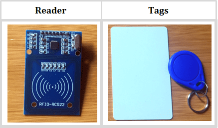
The RFID system consists of two main components, a tag attached to an object to be identified, and a Transceiver also known as Reader.
A Reader consists of a Radio Frequency module and an antenna which generates high frequency electromagnetic field. On the other hand, the tag is usually a passive device, meaning it doesn’t contain a battery. Instead it contains a microchip that stores and processes information, and an antenna to receive and transmit a signal.
To read the information encoded on a tag, it is placed in close proximity to the Reader. The Reader generates an electromagnetic field which causes electrons to move through the tag’s antenna and subsequently power the chip.
The powered chip inside the tag then responds by sending its stored information back to the reader in the form of another radio signal. The change in the electromagnetic/RF wave, is detected and interpreted by the reader which then sends the data out to a computer or microcontroller.
The MFRC255 RFID Reader Module
For most of our RFID based Arduino projects, the MFRC522 RFID Reader/Writer module is a great choice. It is low power, low cost and easy to interface with.
It usually comes with a RFID card tag and key holder tag having 1KB memory. And best of all, it can write a tag, so you can store your some sort of secret message in it.
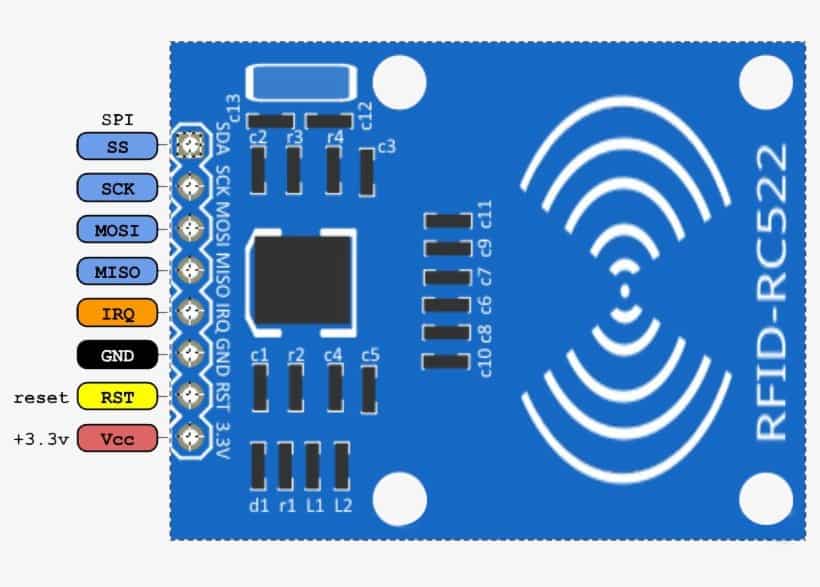
The RC522 RFID Reader module is designed to create a 13.56MHz electromagnetic field that it uses to communicate with the RFID tags. The reader can communicate with a microcontroller over a 4-pin Serial Peripheral Interface (SPI) with a maximum data rate of 10Mbps. It also supports communication over I2C and UART protocols.
The operating voltage of the module is from 2.5 to 3.3V, but the good news is that the logic pins are 5-volt tolerant, so we can easily connect it to an Arduino or any 5V logic microcontroller without using any logic level converter.
- This RFID module and other parts needed in the projects below can be bought from these recommended links:
- MFRC522 RFID Module:….. Amazon
- SG90 Servo Motor:………… Amazon
- 16×2 LCD 12C Display:…… Amazon
Disclosure: These are affiliate links. I earn a commission as an Amazon Associate for qualifying purchases. I would appreciate your support in this way.
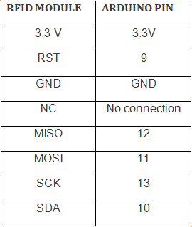
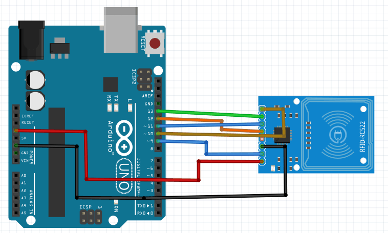
Connecting the MFRC522 RFID module with Arduino
The RFID module is connected depending on the type of board being used. In this case we are using Arduino Uno board and the connection is as shown below
Connection for other Arduino boards can be got from the DumpInfo example sketch from the MFRC522.h library. This is expalined in the next section.
Reading the RFID tag
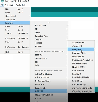
Before doing anything with the RFID module and Arduino, make sure you have MFRC522.h library installed in the Arduino IDE. This library simplifies reading from and writing to RFID tags. You can download the library from here.
Once you have the library installed, open the Examples submenu and of the Arduino IDE. Select MFRC522 > DumpInfo example sketch.
The DumpInfo sketch is uploaded to the Arduino after connecting the RFID reader to test whether the system works. If we run the Serial Monitor and bring the tag near the module, the reader will start reading the tag and all information from the tag will be displayed on the serial monitor.
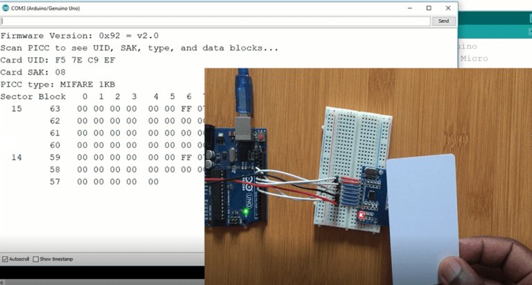
It displays all the useful information about the tag including tag’s Unique ID (UID), the memory size and the whole 1K memory.
The 1K memory of the Tag is organized in 16 sectors (from 0 to 15) Each sector is further divided into 4 blocks (block 0 to 3). Each block can store 16 bytes of data (from 0 to 15).
Making Arduino based RFID Door Lock Access Control System.
We can now use Arduino and MFRC522 RFID module for making one of the commonest use of RFID systems which is security door lock access control. The logic is that only the person with the right information on his card is allowed to enter.
The system is programmed in such a way that when the RFID tag is close enough to be energized by the RC522 reader, it’s UID is scanned. If the UID of this tag matches a predefined value that is stored in Arduino memory, access will be granted and if we scan any unknown tag the access will be denied.
You can also check out these references for the interfacing of the servo motor and I2C lcd with Arduino;
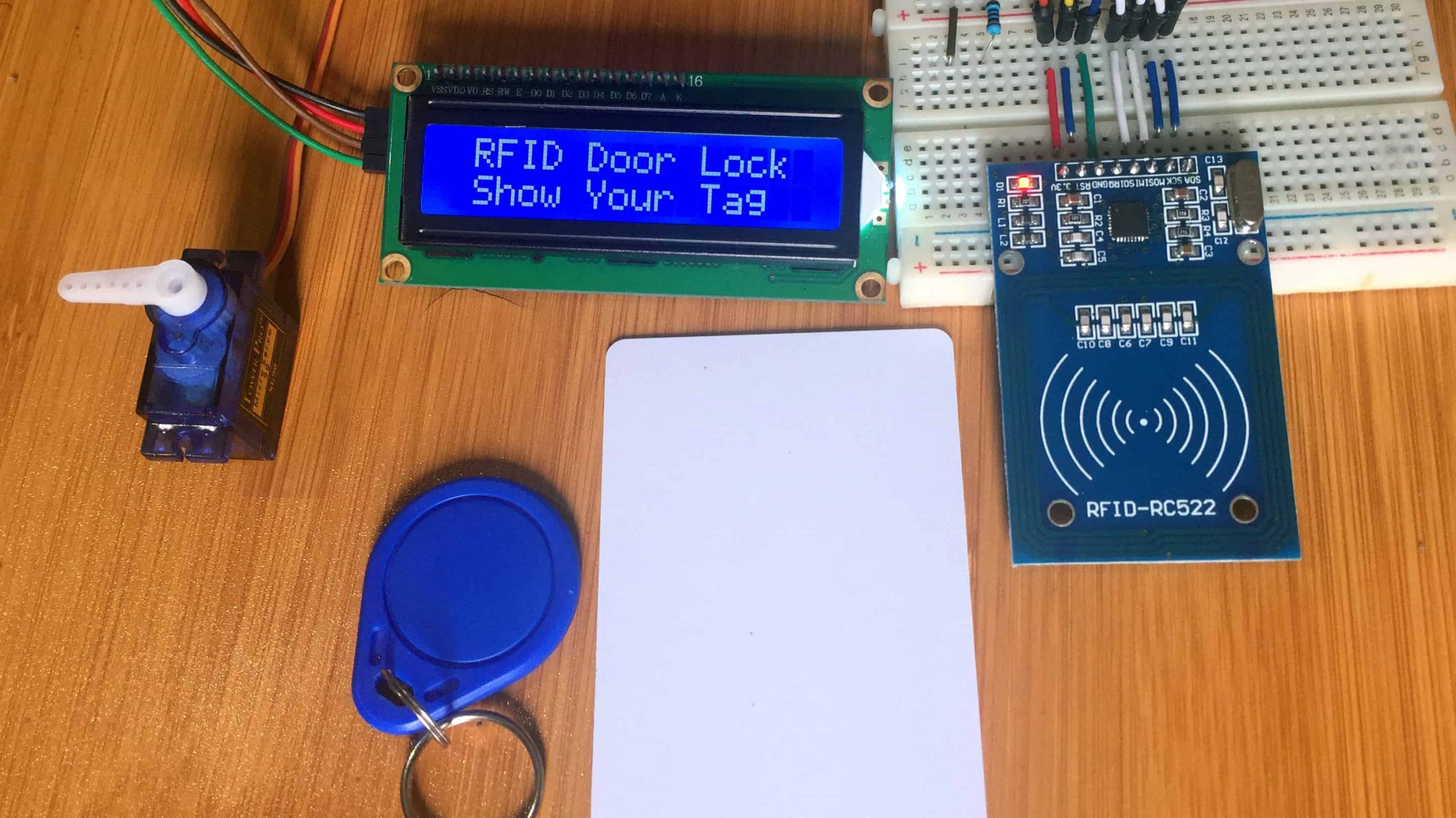
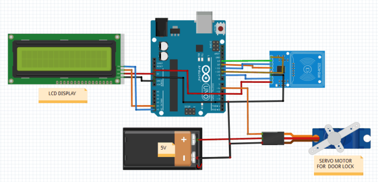
The setup includes the MFRC522 RFID reader connected to the Arduino board. There is an LCD screen to display the state of the lock and a servo motor that demonstrates the movement of the door lock.
Code for the RC522 RFID door lock using Arduino.
 #include <Wire.h>
#include <SPI.h>
#include <LiquidCrystal_I2C.h>
#include <Servo.h>
#include <MFRC522.h>
 LiquidCrystal_I2C lcd(0x27, 2, 1, 0, 4, 5, 6, 7, 3, POSITIVE);
 MFRC522 mfrc522(10, 9); // MFRC522 mfrc522(SS_PIN, RST_PIN)
 Servo myservo;
 int angle=0;
 String tagUID = "F5 7E C9 EF"; // String to store UID of tag. Change it with your tag's UID

 void setup() {
 myservo.attach(6);
 lcd.begin(16,2); // LCD screen
 lcd.backlight();
 SPI.begin(); // Init SPI bus
 mfrc522.PCD_Init(); // Init MFRC522

 lcd.clear();
 }
 void loop() {
 lcd.setCursor(0, 0);
 lcd.print(" RFID Door Lock");
 delay(1000);
 lcd.setCursor(0, 1);
 lcd.print(" Show Your Tag ");

 // Look for new cards
 if ( ! mfrc522.PICC_IsNewCardPresent()) {
 return;
 }
 // Select one of the cards
 if ( ! mfrc522.PICC_ReadCardSerial()) {
 return;
 }

 //Reading from the card
 String tag = "";
 for (byte i = 0; i < mfrc522.uid.size; i++)
 {
 tag.concat(String(mfrc522.uid.uidByte[i] < 0x10 ? " 0" : " "));
 tag.concat(String(mfrc522.uid.uidByte[i], HEX));
 }
 tag.toUpperCase();

 //Checking the card
 if (tag.substring(1) == tagUID) //change here the UID of the card/cards that you want to give access
 {
 // If UID of tag is matched.
 lcd.clear();
 lcd.setCursor(0, 0);
 lcd.print("Access Granted");
 lcd.setCursor(0, 1);
 lcd.print("Door Opened");
 myservo.write(90);
 //digitalWrite(greenLed, HIGH);
 delay(3000);
 //digitalWrite(greenLed, LOW);
 myservo.write(0);
 lcd.clear();
 }

 else
 {
 // If UID of tag is not matched.
 lcd.clear();
 lcd.setCursor(0, 0);
 lcd.print("Wrong Tag Shown");
 lcd.setCursor(0, 1);
 lcd.print("Access Denied");
 delay(3000);
 lcd.clear();
 }
 }
I have also made projects on other Arduino based door lock systems using passwords and Fingerprints which you can refer to from the links below;