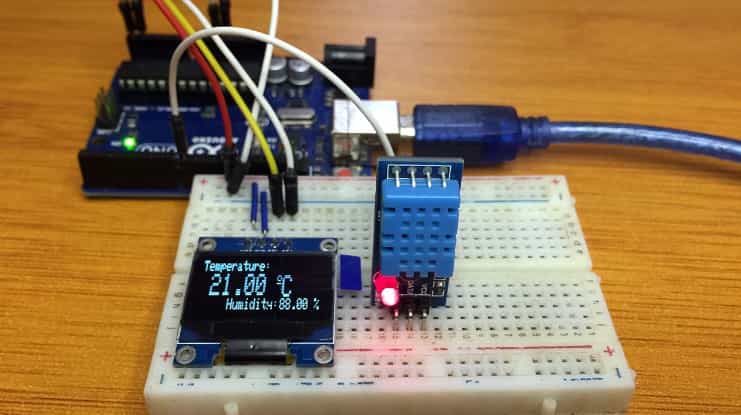
DHT11 Temperature and Humidity sensor with Arduino.
DHT11 humidity and temperature sensor is belongs to the DHTxx family of sensors. These sensors are used in a number of areas where we need to monitor the relative humidity and temperature for example in air conditioning systems, weather stations, storage units for food, medical and industrial supplies and many other applications.
This sensor is highly recommended due to its low cost, precise calibration, durability and because it gives a digital signal output, it is easy to use with a number of microcontrollers including Arduino.
DHT11 Temperature and Humidity sensor hardware overview.
The DHT11 sensor can be got either as a stand-alone sensor having four pins or as a breakout board with the sensor mounted onto a PCB as illustrated below.
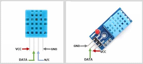
The breakout board version is easier to connect to a microcontroller because all the other components that are required are included on the PCB therefore you just connect the three pins directly.
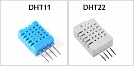
What is the difference between DHT11 and DHT22 sensors?
Without first going into the technical aspects, the first difference between these sensors is the physical appearance where the plastic casing housing the sensor components for DHT11 is blue while for DHT22 it is white.
These sensors have the same pinout but are quite different in characteristics as summarized in the table below;
| Specifications | DHT11 | DHT22 |
|---|---|---|
| Temperature range (Accuracy) | 0°C to +50°C (±2℃) | -40°C to +125°C (±0.5℃) |
| Humidity range (Accuracy) | 20 to 80% (±5% RH) | 0 to 100% (±2 to ±5% RH) |
| Sampling rate | 1Hz | 0.5Hz |
| Operating Voltage | 3.5~5.5V DC | 3.5~5.5V DC |
From the table above, it is obvious that the DHT22 is more accurate and has a wider range for both temperature and humidity measurements. However, this makes it more expensive than the DHT11.
The DHT11 is less costly, smaller in size and has a higher sampling rate than the DHT11. The sampling rate is the amount of time taken for the sensor to give a single data reading.
The sampling rate of the DHT11 is 1Hz meaning that it outputs one reading every second, while the sampling rate of DHT22 is 0.5Hz therefore gives one reading every two seconds.
The sensors use the same voltage of 3.5 to 5V therefore can be used interchangeably depending on the accuracy of your project without changing the wiring. You only need to do some small changes in the operating code.
How does the DHT11 Temperature and Humidity sensor work?
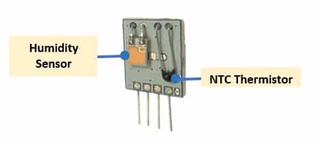
The DHT11 humidity and temperature sensor consists of a resistive type humidity sensor, an NTC (negative temperature coefficient) thermistor for measuring temperature and an 8-bit microcontroller which converts the analog signals from both the sensors and sends out a digital signal.
Humidity measurement
Humidity is the amount of water vapor (moisture)in the atmosphere. The humidity sensing component in the DHT11 consists of two electrical conductors with a non-conducting polymer film present between them.
This film absorbs moisture from air causing a change in voltage levels between the two conducting plates due to change in conductivity. The change in resistance between the electrodes is proportional to the relative humidity where by an increase in humidity decreases the resistance between the electrodes.
Temperature measurement
The sensor uses a Negative Temperature Coefficient (NTC) thermistor for measuring temperature. A thermistor is a “thermal resistor”, that is, its resistance changes with change in temperature.
Unlike other resistors, the thermistors used in DHT11 sensors are made of semiconductor ceramics and other polymers so that a very small change in temperature causes a drastic change in resistance. The resistance decreases with increase of the temperature.
Connecting the DHT11 humidity and temperature sensor to Arduino.
The stand-alone DHT11 sensor has four pins;
- VCC – to 5V power supply
- DATA – to any Arduino digital pin
- NC – not connected
- GND – to ground
A 5kΩ to 10kΩ pull-up resistor is placed across the data line to keep it HIGH by default and to enable better communication between the sensor and the Arduino Board. The connection is done as shown below.
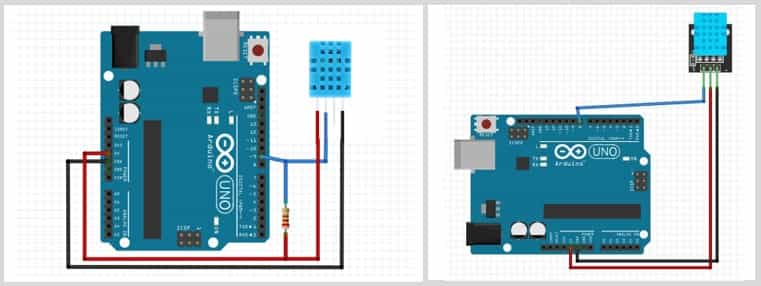
Connecting the DHT11 sensor on a breakout board is straight forward because the pull-up resistor is included on the PCB.
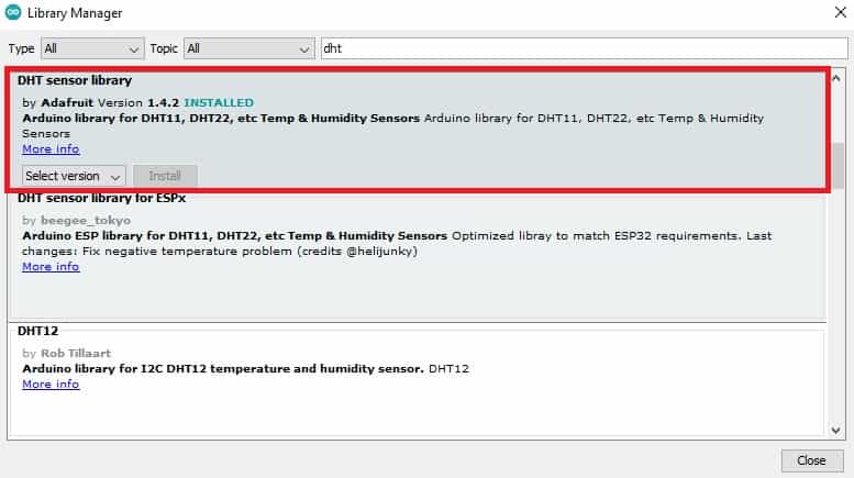
Before you can use the DHT11 on the Arduino, you’ll need to install the necessary library containing the functions needed to get the humidity and temperature readings from the sensor. I found the DHT sensor library from Adafruit easy to use and can be got from the Arduino IDE Library Manager.
Displaying DHT11 humidity and temperature sensor readings on 16X2 LCD.
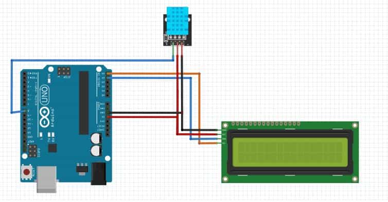
The connection is going to be done as shown below. The data pin of the sensor is connected to digital pin 8 of the Arduino and the VCC and GND for both the sensor and LCD are connected to the 5V and GND pins.
In this case we are using an I2C LCD therefore the SCL and SDA lines of the LCD will be connected to analog pins A5 and A4 respectively for Arduino UNO.
Code for DHT11 humidity and temperature sensor with 16X2 I2C LCD
#include <DHT.h>
#include <LiquidCrystal_I2C.h>
LiquidCrystal_I2C lcd(0x27,16,2);  //0x27 is the i2c address, while 16 = columns, and 2 = rows.

#define DHTPIN 8 // digital pin connected to sensor
#define DHTTYPE    DHT11     // DHT 11

DHT dht(DHTPIN, DHTTYPE);

void setup(){
  Serial.begin(9600);
  dht.begin();        //Initialize the DHT11 sensor
  lcd.begin();        //Initialize the LCD
  lcd.backlight();    //Activate backlight
}

void loop()
{
  float t = dht.readTemperature();
  float h = dht.readHumidity();

  if (isnan(h) || isnan(t)) {
    Serial.println("Failed to read from DHT sensor!");
  }

  lcd.setCursor(0,0);
  lcd.print("Temp: ");
  lcd.print(t);
  lcd.print((char)223);
  lcd.print("C");
  lcd.setCursor(0,1);
  lcd.print("Humidity: ");
  lcd.print(h);
  lcd.print("%");
  delay(1000); // Delay 1 second, as the DHT11 sampling rate is 1Hz
}
First we include the necessary libraries which are DHT.h for the sensor and LiquidCrystal_I2C.h for controlling the I2C LCD.
Then we declare the type of sensor in use which is DHT11 and the digital pin where the sensor is connected.
A dht() method is created with the digital pin and sensor type as arguments.
In the setup(), we initialize the DHT11 sensor using dht.begin() and the I2C LCD is initialized using lcd.begin().
In the loop() section, we get the temperature in ⁰C and humidity readings from the sensor using the readTemperature() and readHumidity() methods respectively. Then these readings are displayed on the LCD using the print() method.
To get the temperature in ⁰F we use the readTemperature(true) method.
You can also make reference to the post below on how to use the 16×2 I2C LCD with Arduino.
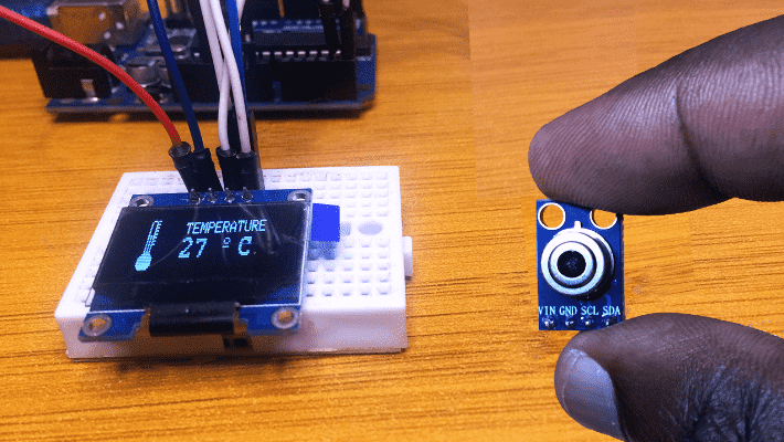
Displaying DHT11 humidity and temperature sensor readings on I2C OLED.
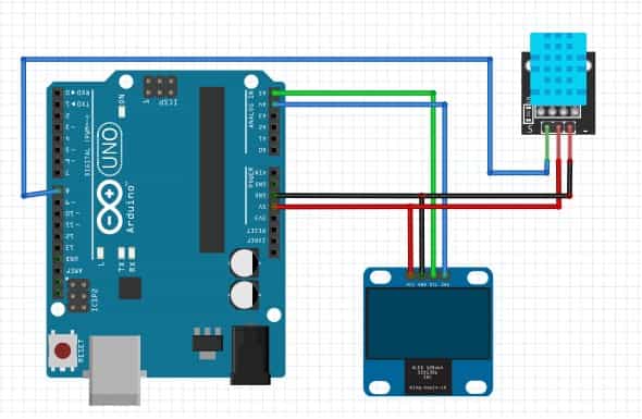
The I2C OLED and DHT11 sensor are connected as shown in the schematic below.
Code for DHT11 humidity and temperature sensor with OLED.
#include <Wire.h>
#include <Adafruit_GFX.h>
#include <Adafruit_SSD1306.h>
#include <Adafruit_Sensor.h>
#include <DHT.h>

#define SCREEN_WIDTH 128 // OLED display width, in pixels
#define SCREEN_HEIGHT 32 // OLED display height, in pixels

#define OLED_RESET -1
Adafruit_SSD1306 display(SCREEN_WIDTH, SCREEN_HEIGHT, &Wire, OLED_RESET);

#define DHTPIN 8 // digital pin connected to sensor
#define DHTTYPE    DHT11     // DHT 11
//#define DHTTYPE    DHT22     // DHT 22 (AM2302)


DHT dht(DHTPIN, DHTTYPE);


void setup() {
  Serial.begin(115200);
  dht.begin();
  display.begin(SSD1306_SWITCHCAPVCC, 0x3C);
  delay(2000);
  display.clearDisplay();
  display.setTextColor(WHITE);
}

void loop() {
  float t = dht.readTemperature();
  float h = dht.readHumidity();
  if (isnan(h) || isnan(t)) {
    Serial.println("Failed to read from DHT sensor!");
  }

  //clear display
  display.clearDisplay();

  // display temperature
  display.setTextSize(1);
  display.setCursor(0,0);
  display.print("Temperature: ");
  display.setTextSize(2);
  display.setCursor(10,9);
  display.print(t);
  display.print(" ");
  display.setCursor(80,10);
  display.setTextSize(1);
  display.cp437(true);
  display.write(167);
  display.setTextSize(2);
  display.print("C");

  // display humidity
  display.setTextSize(1);
  display.setCursor(30, 25);
  display.print("Humidity: ");
  display.setTextSize(1);
  display.setCursor(85, 25);
  display.print(h);
  display.setCursor(115, 25);
  display.print(" %");

  display.display();
}
The working of the code is similar to the one already discussed in the example with the I2C LCD. The only difference is that in this case we are adding libraries for the I2C OLED.
For a more detailed reference on the functions for displaying text and characters on the OLED you can visit the link below;