DIY Lithium-ion 18650 Battery Charger using TP4056 Module.
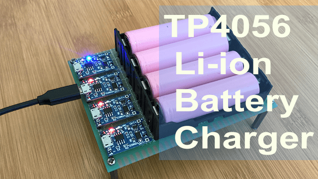
Rechargeable batteries are among the most used power sources for electronic devices and in this tutorial, I would like to show you how to make a simple lithium battery charger using TP4056 module with battery protection.
TP4056 Module features.
This module is made for charging rechargeable lithium batteries using the constant-current/constant-voltage charging method. There are two types of Lithium battery charger TP4056 modules on the market, with and without protection IC.
For this tutorial I’ll focus on the TP4056 battery charger module with battery protection containing components as shown below.
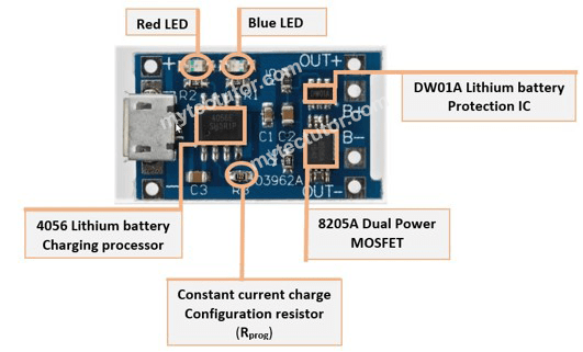
This module uses the TP4056 Li-ion charge controller IC and a separate DW01A Li-ion battery protection IC which provides the following features;
- Over-discharge protection which keeps your battery from being discharged below 2.4V, a healthy minimum voltage level for your battery. If a connected battery has been discharged below 2.4V the module will cut output power from the battery until the battery voltage has been re-charged above 3.0V (the over-discharge release voltage), which at that time the module will again allow discharge of power from the battery to a connected load. Although the module cuts output power from the battery during an over-discharge situation, it still allows charging of the battery to occur through the parasitic diode of the discharge control MOSFET (FS8205A Dual MOSFET).
- Overcharge protection – the module will safely charge your battery to 4.2V.
- Overcurrent and short-circuit protection – the module will cut the output from the battery if the discharge rate exceeds 3A or if a short-circuit condition occurs.
- Soft-start protection which limits inrush current.
- Trickle charge (battery reconditioning) – if the voltage level of the connected battery is less than 2.9V, the module will use a trickle charge current of 130mA until the battery voltage reaches 2.9V, at which point the charge current will be linearly increased to the configured charge current.
Rprog Resistor – This is used for externally configuring the charge current. You can check the TP4056 module datasheet which includes a table and equation for what resistor values to use for configuring different charge currents.
Status LEDs – The Red LED indicates that the battery is charging and Blue(green) LED shows that the battery is full charged. If no battery is connected, the blue LED also lights and the red LED will be flashing.
Power supply for the TP4056 module
This charging module can be powered from a 5V 1A DC voltage supply connected via the solder pads marked IN+ and IN-. Alternatively, you can use a micro-USB cable like the one used for smart phone chargers.

If you use a micro-USB connection, make sure the USB cable is made to carry at least 1A. Most modern smart phone USB chargers can provide 1A or more but always check the label on your phone charger to verify before use.
Connecting Lithium battery to the TP4056 module
The charger module has a number of solder pads where the battery to be charged is connected as shown below.
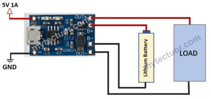
- B+ and B– (or BAT+ and BAT-) for connecting the Li-ion battery to be charged.
- IN+ and IN– are the alternative power supply connection pads
- OUT+ and OUT- for connecting a load (something for the Li-ion battery to power).
The load should be disconnected when charging the battery. You can use an on and off switch with the load to avoid charging and discharging the battery simultaneously.
It is possible to connect two lithium batteries in parallel to the TP4056 module to form an equivalent single cell battery with a total capacity of twice that of the individual single cells.
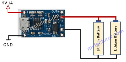
When charging two cells in parallel, both cells must be at the same voltage level otherwise if one cell has a lower voltage than the other cell, the higher voltage cell will discharge into the lower voltage cell in order to bring the two cells to the same voltage, which will eventually balance out. If the voltages of the two cells differ significantly the resulting current through both cells can be high enough to cause the cells to overheat and even destroy the cells.
Because of the above reason, it is recommended to use only one battery cell for each TP4056 module and never use more than two cells at a time with a single module
DIY 18650 Li-ion battery charger using TP4056 modules.
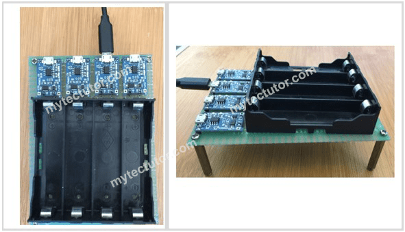
I will now proceed to demonstrate how you can make a simple Lithium battery charger unit using TP4056 modules and 18650 Lithium battery holder. The connections can be done as shown below. In my case am making a four-battery charger unit but you can extend this concept to even more units.
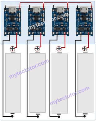
The connections can be made using wires or solder or better still you can design a PCB for your charger unit. The finished product will appear as shown below.
Hope you can now be able to make your own low-cost lithium battery charger unit.
