How To Use A Water Flow Sensor With Arduino.
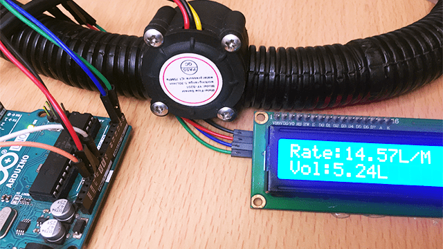
Water flow sensors are used in a number of applications where it is necessary to measure the rate and volume of water and other liquids for example in smart irrigation systems, automatic water dispensers, water vending machines, water treatment plants, leak detection systems, aquariums, coffee machines and other uses.
In this tutorial am going to give a detailed overview of the YF-S201 water flow sensor and how it can be interfaced with Arduino to measure the rate of flow and volume of water.
YF-S201 Water Flow sensor Hardware Overview
The YF-S201 water flow sensor is made of a plastic casing containing inlet and outlet valves, a rotor or turbine wheel whose shaft is connected to a magnet and a Hall effect sensor that is properly sealed off to avoid contact with water. The image below show what you will see when you open the the plastic casing.
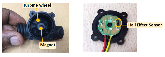
The sensor has three wires colored red for VCC, black for GND and yellow for the pulse output
Specifications of the YF-S201 water flow sensor
- Operational Voltage: 4.5 – 18 Volts
- Maximum Current draw: 15 mA @ 5V
- Flow Rate Capacity: 1 -30 L/min
- Maximum Water pressure : 2 MPa
- Operational Temperature: -25 to +800C
- Working Humidity range:35%-80% RH
- Accuracy: ±10%
How does a Water Flow Sensor work?
This sensor works on the Hall effect principle. When water or any other liquid is passed through the sensor, it strikes and rotates the turbine wheel which has a magnet attached to it. The speed of rotation of the wheel interferes with the magnetic flux and this interference is sensed by the Hall effect sensor which in turn generates a pulse signal for every revolution that the rotor makes.
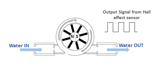
The pulse signals from the Hall effect sensor will be the output at the signal pin and the number of pulses is directly proportional to the rotational speed of the turbine. By connecting the output signal to a microcontroller like Arduino, we can be able to determine the rate of flow of a given liquid by counting the number of pulses produced in one second or minute.
Connecting Water Flow sensor to Arduino.
To connect the water flow sensor to Arduino, the red wire is connected to 5V, black to GROUND and yellow to an interrupt pin of Arduino. Interrupt pins vary depending on the type of Arduino board you are using. For Arduino Uno and Nano the interrupt functionality is only available on pins 2 and 3. If you are using the Arduino Mega, interrupt pins are 2, 3, 18 and 20.
The connection is done as shown in the schematic diagram below;
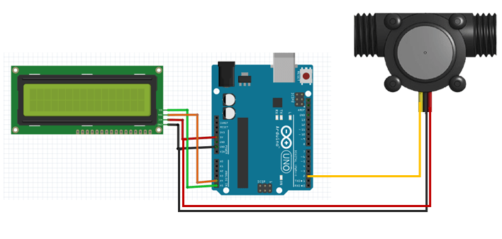
I have also connected an I2C LCD to be able to display the flowrate and volume being measured by the sensor.
You can connect a flexible conduit to the sensor to enable easy flow of water in and out of the sensor.
Code for water flow sensor with Arduino and I2C LCD.
#include <LiquidCrystal_I2C.h>

volatile int flow_frequency;
float vol = 0.0,l_minute;
unsigned char flowsensor = 2; // Sensor Input
unsigned long currentTime;
unsigned long cloopTime;

LiquidCrystal_I2C lcd(0x27, 16, 2);

void flow () // Interrupt function to increment flow
{
   flow_frequency++;
}
void setup()
{
   pinMode(flowsensor, INPUT);
   attachInterrupt(digitalPinToInterrupt(flowsensor), flow, RISING); // Setup Interrupt

   lcd.begin();
   lcd.backlight();
   lcd.clear();
   lcd.setCursor(0,0);
   lcd.print("Arduino FlowMeter");
   currentTime = millis();
   cloopTime = currentTime;
}

void loop ()
{
   currentTime = millis();
   // Every second, calculate and print litres/hour
   if(currentTime >= (cloopTime + 1000))
   {
    cloopTime = currentTime; // Updates cloopTime
    if(flow_frequency != 0)
    {

       l_minute = (flow_frequency / 7.5); // (Pulse frequency x 60 min) / 7.5Q = flowrate in L/hour
      lcd.clear();
      lcd.setCursor(0,0);
      lcd.print("Rate: ");
      lcd.print(l_minute);
      lcd.print(" L/M");
      l_minute = l_minute/60;
      lcd.setCursor(0,1);
      vol = vol +l_minute;
      lcd.print("Vol:");
      lcd.print(vol);
      lcd.print(" L");
      flow_frequency = 0; // Reset Counter
    }
    else {
      lcd.clear();
      lcd.setCursor(0,0);
      lcd.print("Rate: ");
      lcd.print( flow_frequency );
      lcd.print(" L/M");
      lcd.setCursor(0,1);
      lcd.print("Vol:");
      lcd.print(vol);
      lcd.print(" L");
    }
   }
}
Code description
First include the LiquidCrystal_I2C library for controlling the I2C LCD and also declare the flow_frequency, vol, flowsensor, currentTime and cloopTime variables.
The flow() function is an interrupt service routine and is called every time there is an interrupt signal at pin2. For every interrupt signal, the count of the variable flow_frequency will be increased by 1.
In the setup() section, first we declare the Arduino pin to which the signal pin of the flow sensor is connected as an input pin and then configure the interrupt using attachInterrupt() method. This takes on arguments which are the interrupt number, the function you would like to run when triggered and what you would like to set as the trigger. In this case am are using interrupt 0 to trigger the flow() function when the pin changes from low to high which is a “RISING” edge interrupt.
Next, we initialize the I2C LCD and call the millis() function to keep track of time.
In the loop() section, first compare how much time has elapsed since the last loop. The l_minute variable is used to calculate the flowrate in liters per hour and the vol variable gives the volume in liters. The value of the flowrate and volume will be displayed on the LCD.
To understand the mathematics involved in calculating the flowrate and volume, it is important to take note of the following:
From the datasheet of this sensor, the Flow rate pulse characteristic is given as;
- Pulse frequency (Hz) = 7.5Q where Q is the flow rate in Liters/minute
- Flow Rate (Liters/hour) = (Pulse frequency x 60 min) / 7.5Q
And to get the volume of water passing through the sensor in liters we use the formula
- Volume(liters) = Q * time elapsed (seconds) / 60 (seconds/minute)
- Volume(liters) = (Frequency (Pulses/second) / 7.5) * time elapsed (seconds) / 60
- Volume(liters) = Pulses / (7.5 * 60)
When the above code is uploaded to Arduino and water is passed through the sensor, you will see values of flow rate and volume of water in liters on the I2C LCD.
Limitations of the YF-S201 water flow sensor
From the specifications of this sensor, it is efficient for measuring flow rate of liquids in the range of 1~30L/min therefore the YF-S201 water flow sensor is not suitable when dealing with liquids having high flow rates and pressure.
The accuracy of this sensor is also affected by low viscosity liquids, corrosive liquids and suspended particles in liquids which can clog the turbine wheel.
