The 8051 family of microcontrollers are 8 bit microcontrollers developed by Intel in the 1980’s although today they are not as popular as other microcontrollers like the ARM, AVR and PIC microcontrollers. However if you really want to learn the basics of microcontroller programming then the 8051 should be the first choice before moving on to the more advanced microcontrollers.
In this tutorial I want to give a detailed explanation of how to begin the programming and application of the 8051 microcontroller. I will not go deep into the architecture and working principles but mainly give an overview of the hardware and software needed to begin.
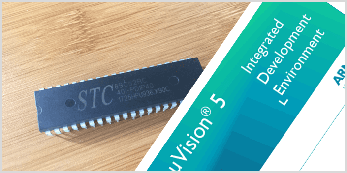
Overview of the 8051 Microcontroller IC hardware.
The 8051 microcontroller comes in different packages although the pin configuration remains the same. The commonest package is the 40 pin Dual In-line Package (DIP) like the example shown in the figure below.

Pin description
Port 0 (P0.0 to P0.7): From Pin32 to 37 and is an 8-bit bidirectional Input / Output Port with no internal pull up resistors therefore you need to add external pull-up resistors in order to use this port pins as I/O pins.
Port 1 (P1.0 to P1.7): From Pin 1 to 8 and is also an 8-bit bidirectional I/O port with internal pull up resistors.
Port 2 (P2.0 to P2.7): From Pin 21 to 28 and used as an 8-bit bidirectional I/O port like ports 0 and 1. When external memory is to be accessed, this port is used as a bidirectional higher address byte and data bus.
Port 3 (P3.0 to P3.7): From Pin 10 to 17 which is also an 8-bit bidirectional I/O port with internal pull up resistors. Apart from being used as I/O port, the pins also have other functions as shown in the table below.

RST (Pin 9): This is the Reset Input pin and is an active HIGH pin. When this pin is HIGH for at least two machine cycles, all the registers and ports of the microcontroller will be reset to their default states.VCC (Pin 40): 5V Power supply pin.
GND (Pin 20): Ground pin of the microcontroller.
XTAL2 and XTAL1 (Pin 18 and 19): For connecting an external oscillator and normally we use a Quartz Crystal Oscillator.
PSEN (Pin 29): Program Store Enable Pin and is used when there is need for reading external Program Memory.
ALE/PROG (Pin 30): Address Latch Enable Output pin used when connecting to external memory chips. In 8051, the lower 8 bits of the 16-bit address bus are multiplexed with the data bus and to separate these 8 bits, the ALE pin is kept high. PROG is the Program Pulse Input and is used when we are programming the flash memory of the 8051 microcontroller.
EA/VPP (Pin 31): External Access Enable Pin and is used to access external Program Memory. The code from an external program memory can be accessed only if this pin is LOW. For normal operations, this pin is kept HIGH.
Writing programs for 8051 Microcontroller using Keil IDE.
Programs for running the 8051 microcontroller are mainly written in C and Assembly languages. The commonest IDE for writing programs for this device is Keil µVision which contains an editor, a C compiler, an assembler, a linker, library and a Hex converter.This IDE can be downloaded from here. To download the Keil IDE click on the icon with C51.
Steps in writing code using Keil µVision IDE.
1. Before opening the IDE first create a folder where all the other project folders and files will be stored.
2. Then open the Keil Vision IDE and go to Project > New µVision Project and then give your new project a name. This project should be inside the folder created in step 1 above.

3. Select STC MCU database and the type of chip you are using

4. By default, Keil does not add/create any file and so you’ll see that the project folder has no main source file. We’ll have to create one main source file and add additional files if needed.
To create a new file go to File > New. A text file will be created and then save it with a name with an extension depending on the type of code written. If the code is in Assembly language use “.asm” and for C language use “.c” extensions.

5. You observe that the project has a Source Group folder inside Target 1 folder. The created file in step 4 above should be inside the Source Group folder. This is done by right clicking on Source Group > Manage Project Items.
Click on Add Files and then locate where the file you created is in the project folder. Click on Add and then Ok.

You can now observe that the text file created is now under the Source Group folder. After this step then you can begin writing the code.
6. Since the code is written in a high level language like Assembly or C language, it has to be converted to Hex code which is the machine readable format. To do this you have to Right Click on Target1 > Options for Target and the window below will be opened.

Make sure the Create HEX File option is ticked. This will enable creation of HEX code when you compile the written code.
7. After writing the code you need to check if the code has any errors or not and to do this click Project> Rebuild all Target Files

Hardware for programming the 8051 microcontroller.
After writing the code, you need a way of uploading the code to the microcontroller and this is done in a number of ways. The simplest way is by using a USB ISP programmer like the one shown below.
This programmer has a Zero Insertion Force (ZIF) socket for holding the microcontroller and a USB cable with a Type-A connector into the computer and a Type-B connector to the programmer.

There are a number of designs for 8051 development boards you can find online and they also work just as well.
Alternatively if you are good with circuit and PCB design, you can make your own circuit to run the 8051 microcontroller like my simple DIY 8051 development board below. In this case I use a USB-TTL auto programmer to upload code into the microcontroller.

Basic Connections of the 8051 Microcontroller Circuit.
If you are interested in making your own circuit for programming this microcontroller then you need to know the basic circuit connections which are as shown in the schematic below.

There are three main circuits;
Power supply: Connect Pin 40(VCC) and Pin 20(GND) to 5V and ground respectively.
Reset circuit: Pin 9 is used as a manual reset and consists of a 10µF capacity, a 10kΩresistor and a push button. If there is no push button, this circuit will be a power-on reset circuit.
Clock circuit: Consists of a Quartz Crystal Oscillator connected across XTAL1 and XTAL2 pins. Capacitors C1 and C2 are in the range 20pF and 40pF.
Remember that Port 0 has no internal pull-up resistors unlike Ports1, 2 and 3 therefore you need to add external pull-up resistors by applying a 1kΩ resistor pack with 8 resistors.
Uploading Code to the Microcontroller.
Since the code is written in Assembly or C language, it has to first be converted to Hex code which is the machine readable format and then using this ISP software to upload this Hex code to the microcontroller.
There is different software you can use to upload code to the 8051 microcontroller for example the STC-ISP programming software tool which can be downloaded from the here. This tool can upload Hex code to a number of microcontrollers from various manufacturers and most probably will work fine with your chip.
After connecting the microcontroller to your computer using a USB programmer, open the STC-ISP tool and its dashboard looks as shown below. I have marked the main buttons to check in the tool before uploading code to the microcontroller.

1. Specify the MCU type you are using for example in the above case it is STC89C51RC.
2. Select the COM port where the microcontroller is connected on the computer.
3. Check if the MCU is working properly before uploading code.
4. Open the file containing the Hex code. If the code was written using Kiel IDE this file is inside the objects folder.
5. Upload the Hex code to the microcontroller.
With the above introduction you can now be able to begin using different types of 8051 microcontrollers in a number of applications as will be discussed in the coming tutorials.