The nRF24L01 transceiver modules provide ability to have two or more microcontroller platforms communicating wirelessly among each other which can be very important in some projects including home automation, robotics, game controllers to mention but a few.
Wireless communication among microcontrollers can be achieved in a number of ways including WiFi, GSM/GPRS, Bluetooth, RF, LoRaWAN among others.
In this tutorial I am going to demonstrate how wireless communication between Arduino modules can be achieved using the low cost RF (radio frequency) based nRF24L01+ transceiver modules.
Why use the nRF24 L01+ Transceiver modules?
1. The first advantage of these modules is their low cost. You can buy one for less than $2.
2. nRF24L01+ modules are easy to interface to a variety of microcontrollers like MCU, ARM, PIC, AVR and STM32 using SPI protocol.
3. An operating frequency of 2.4GHz enables higher bit rate usages compared to lower operating frequencies. The Nrf24L01+ module uses GFSK modulation for data transmission hence the data transfer rate can either be 250kbps, 1Mbps or 2Mbps.
4. The operating voltage for these modules is from 1.9 to 3.6V although the logic pins are tolerant to 5V therefore can easily be connected to any 5V logic microcontroller without using any logic level converter. The power consumption is about 12mA during transmission which is even lower than a single LED therefore making this the best choice for wireless device in low power applications.
Hardware Overview of nRF24L01+ Wireless Transceiver modules.
These modules come in various forms but the most popular ones are the two I have shown below.

The first module comes with an onboard antenna hence it is small and compact in size. This module is good for projects in a compact space. However, due to the onboard antenna, it has a short transmission range which makes it unsuitable in certain applications. This module has a transmission range of about 100 meters.
The second version has an external IPX antenna and is designed with a power amplifier. It has a RFX2401C range extender chip which allows the module to have a wider transmission range of up to 1000 meters.
Pinout for the nRF24L01+ transceiver module

GND – Ground pin
VCC- Power supply for the module. Since the module uses 1.9V to 3.9V we should connect it to the 3.3V pin of the Arduino.
CE- Chip Enable. It is an active HIGH pin and it determines whether the Nrf24l01 is transmitting or receiving data depending on this pin’s current mode.
CSN-Chip Select Not. It is an active LOW pin but it is normally kept HIGH so that when it turns LOW the Nrf24l01 begins listening to its SPI port for data processing.SCK- Serial Clock for accepting clock pulses from the SPI bus master.
MOSI- Master Out Slave In which is the SPI input to the nRF24L01 module.
MISO- Master In Slave Out is the SPI output from the nRF24L01 module.
IRQ- This is an interrupt pin but in most of the projects with Arduino it is not used.
How the nRF24L01+ transceiver module works.
The nRF24L01+ transceiver module transmits and receives data on a certain frequency called Channel. Also in order for two or more transceiver modules to communicate with each other, they need to be on the same channel. This channel could be any frequency in the 2.4 GHz ISM band or to be more precise, it could be between 2.400 to 2.525 GHz.
Each channel occupies a bandwidth of less than 1MHz. This gives us 125 possible channels with 1MHz spacing. So, the module can use 125 different channels which give a possibility to have a network of 125 independently working modems in one place.
When connected to a microcontroller, the nRF24L01+ module uses the Serial Peripheral Interface (SPI) communication protocol which uses the concept of a master and slave. In the most applications Arduino is the master and the nRF24L01+ transceiver module is the slave. The number of slaves on the SPI bus is limited and for the Arduino Uno we can have a maximum of two SPI slave devices, that is , two nRF24L01+ transceiver modules.
Connecting nRF24L01+ transceiver module to Arduino.
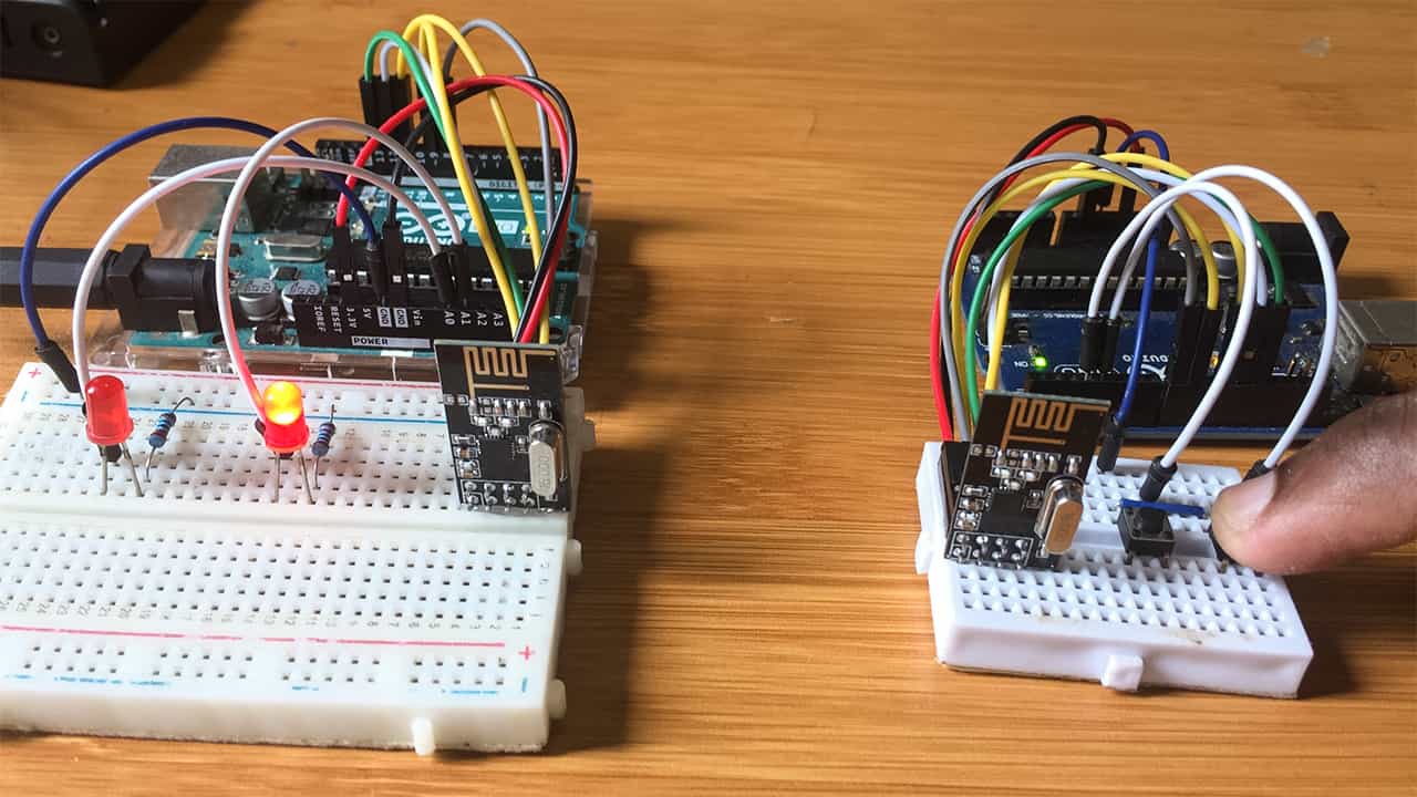
The connection involves two Arduino boards where one acts as a transmitter and another as a receiver. However the nRF24l01+ modules are connected the same way to both boards.
The VCC pin of the module is connected to 3.3V of the Arduino and GND pin to ground. The CSN and CE pins can be connected to any digital pin on the Arduino. In my case, these are connected to digital pin8 and 9 respectively.
For SPI communication, we use the hardware SPI pins of the microcontroller since the nRF24L01+ transceiver module requires a lot of data transfer. Different types of Arduino boards have different SPI pins. Since I am using Arduino UNO board, the pins are digital pin13 for SCK, pin 12 for MISO and pin 11 for MOSI. These are the same pins used for the Arduino Nano.
If you have a different board then you can make reference to the corresponding datasheet for example for the Arduino Mega, we use digital pin 50 for MISO, pin 51 for MOSI and pin 52 for SCK.
For the example below we are going to include two push buttons on pins 3 and 4 of the transmitter and two LEDs on analog pins A0 and A1 of the receiver. When a button from the transmitter is pressed, a corresponding LED will light.

Code for nRF24L01+ with Arduino wireless communication.
To simplify the coding using the nRF24L01 module with Arduino we use the RF24 library. This library has the functions for wireless communication between the Arduino boards
Download the RF24 library: RF24 Library
Since we are using two Arduino boards, we shall have two code files, one for the transmitter and the other for the receiver. The codes are similar in many ways but differ in some aspects as will be discussed below.
Transmitter Code
#include <SPI.h>
#include <nRF24L01.h>
#include <RF24.h>

#define buttonPin1 3
#define buttonPin2 4

int buttonState1 = 0;
int buttonState2 = 0;
RF24 radio(9, 8); // CE, CSN

const byte address[6] = "00002";

void setup() {
  pinMode(buttonPin1, INPUT_PULLUP);
  pinMode(buttonPin2, INPUT_PULLUP);
  Serial.begin(9600);
  radio.begin();
  radio.openWritingPipe(address);
  radio.setPALevel(RF24_PA_MIN);
  radio.stopListening();
}
void loop() {
  buttonState1 = digitalRead(buttonPin1);
  buttonState2 = digitalRead(buttonPin2);

  if (buttonState1 == 1)
  {
    buttonState1 = 1;
  }
  else  if (buttonState1 == 0)
  {
    buttonState1 = 0;
  }
  if (buttonState2 == 1)
  {
    buttonState2 = 3;
  }
  else  if (buttonState2 == 0)
  {
    buttonState2 = 2;
  }
  Serial.print(buttonState1);
  Serial.print("\t");
  Serial.println(buttonState2);
  radio.write(&buttonState1, sizeof(buttonState1));
  radio.write(&buttonState2, sizeof(buttonState2));
}
Receiver Code
#include <SPI.h>
#include <nRF24L01.h>
#include <RF24.h>

#define led1 A0
#define led2 A1

int buttonState = 0;

RF24 radio(9, 8); // CE, CSN
const byte address[6] = "00002";

void setup() {
  Serial.begin(9600);
  pinMode(led1, OUTPUT);
  pinMode(led2, OUTPUT);
  digitalWrite(led1, HIGH);
  digitalWrite(led2, HIGH);
  radio.begin();
  radio.openReadingPipe(0, address);
  radio.setPALevel(RF24_PA_MIN);
}
void loop() {
  radio.startListening();
  while (!radio.available());
  radio.read(&buttonState, sizeof(buttonState));
  Serial.println(buttonState);

  if (buttonState == 1) {
    digitalWrite(led1, LOW);
  }
  else  if (buttonState == 0) {
    digitalWrite(led1, HIGH);
  }
  else if (buttonState == 3) {
    digitalWrite(led2, LOW);
  }
  else  if (buttonState == 2) {
    digitalWrite(led2, HIGH);
  }
}
Description of code for the working of the nRF24L01 Transceiver.
- Both code sketches begin by including the SPI.h library for handling SPI communication and the nRF24L01.h and RF24.h libraries control the module.
- Then create RF24 object with two arguments taking the CE and CSN pins as parameters. In this case we are using pin 8 and 9 respectively.
- Create a byte array for the address or pipe through which the two modules communicate. This can be any 5 letter string.
- To initialize the radio object for Transmitter we use the radio.begin() function. The
radio.openWritingPipe()function is for setting the address of the transmitter while for setting address of the Receiver we useradio.openReadingPipe(). - The
radio.setPALevel()function is for setting the Power Amplifier level, in this case since the modules are close to each other we set it to minimum. - The
radio.stopListening()function sets module as transmitter while theradio.startListening()sets module as receiver.
- The
radio.write()function is for sending message to receiver. This function has two arguments, that is, the first argument is the message that we want to send and the second argument is the number of bytes present in that message. The symbol “&” indicates the variable that stores the data to be sent andsizeof()gets all bytes of the variable. Through this method, you can send up to 32 bytes at a time. Because that is the maximum size of a single packet nRF24L01+ can handle.
- For the receiver, the
radio.available()function is used to check whether there is data to be received. This method returns TRUE value if we any data is available in the buffer. - The
radio.read()function reads and stores data into a variable like buttonState which is then used to control the state of LEDs.
How to Boost the RF Signal.
The main concern of any wireless communication system is the communication range and this is what decides the kind of device to use for a specified application. For better transmission range of the nRF24L01+ module we can look into the following solutions.
1. Reducing the power supply noise by using bypass capacitors of about 4.7 to 47µF across the GND and 3.3V of the modules so that they have more stable voltage while operating. This can easily be achieved by using an adapter module for nRF24L01.
2. Changing your channel frequency to reduce noise from other neighboring wireless network signal sources especially WiFi. It is usually advisable to use between 2.40 and 2.524GHz for the nRF24L01+ module. In the code the frequency can be set using the radio.setChannel() function. For example if we use radio.setChannel(21) then the modules will communicate at 2.421 GHz.
3. Loweing the data transmission rate significantly improves the range. In the code the data rate is set using the radio.setDataRate() function. An argument of RF24_250KBPS signifies 250 kbps, which is the slowest speed available and it offers the longest range of data transmission. RF24_1MBPS signifies 1Mbps and RF24_2MBPS signifies 2 Mbps, giving a higher transfer speed, but less range.
4. Using higher output power which can be adjusted in the code using the radio.setPALevel() function. These values can be RF24_PA_MIN, RF24_PA_LOW, RF24_PA_HIGH, and RF24_PA_max.


