One of the challenges of using LCD displays is that they need many I/O pins of the microcontroller which limits it’s functionality. Normally the LCD utilizes 6 of the available 13 digital IO pins, then you are left with just 7 pins for interfacing other components.
This problem is solved using the I2C backpack which will prevent us from using the digital I/O pins of the Arduino.
The PCF8574 IC based backpack.
The PCF8574 IC based backpack enables us to expand the Arduino’s I/O pins via I2C interface.
You can configure 8 bidirectional I/O pins using just two lines of the I2C interface, that is, the Serial Data line (SDA) and the Serial Clock line (SCL).

The PCF8574 IC based backpack is attached to the back side of the lcd as shown below.

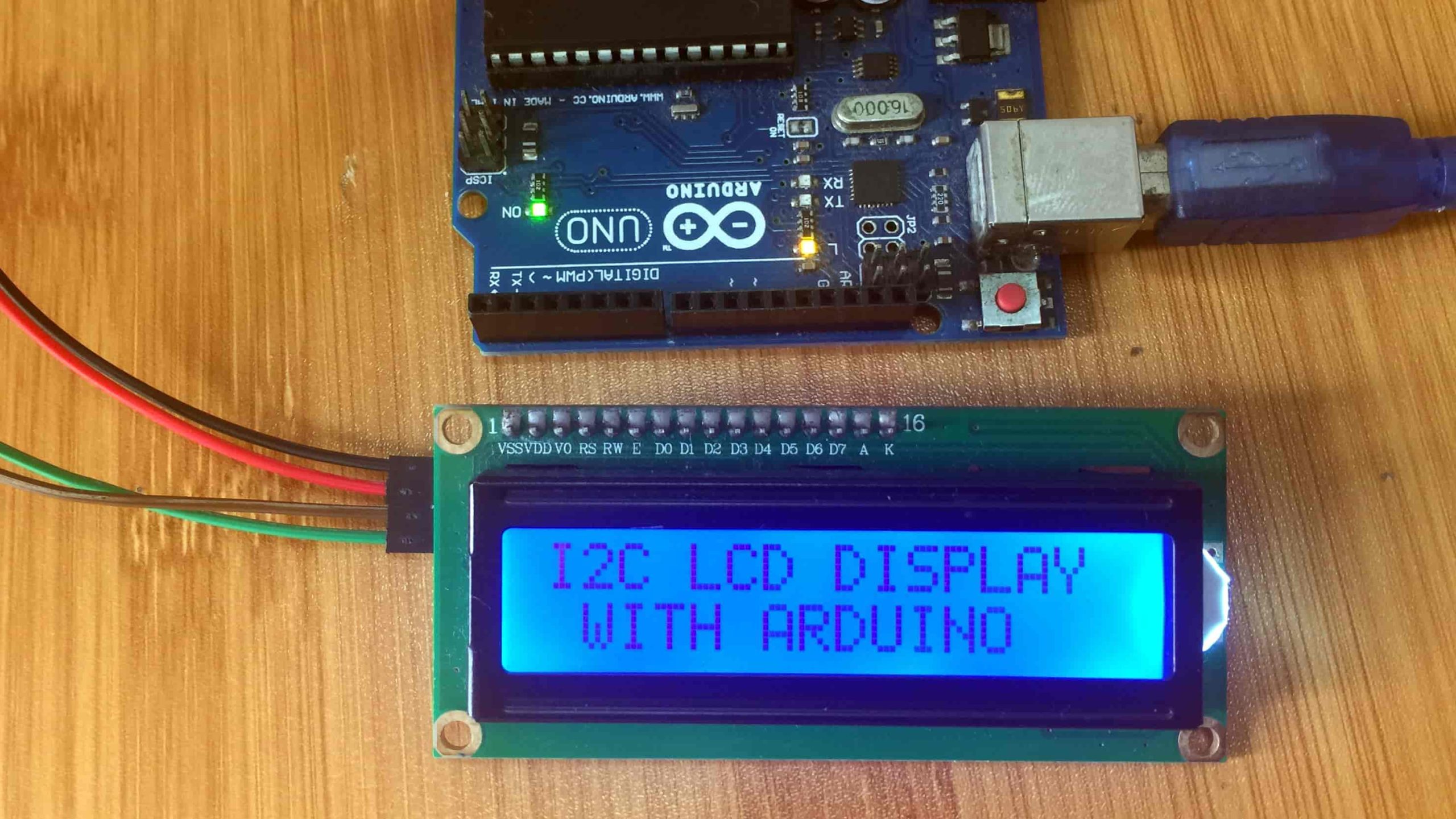
Connecting the 16×2 I2C LCD to Arduino
We connect i2c pins module as shown in the schematic below. VCC of the i2c module to 5V pin and connect the GND as well. The SDA pin of the i2c module connected to Arduino A4 and the SCL pin to A5.

The LCD’s SDA and SCL pins are connected according to the table below for the different Arduino boards:

Before writing the code to display content on the LCD , we need to know the address of the I2C device attached to the LCD. This is done using the I2C Scanner code shown below. This code requires the Wire.h library. PCF8574 chips are set to hexadecimal addresses from 0x20 to 0x27. PCF8574A chips are set to 0-38 through 0x3F.
I2C Scanner code
// i2c_scanner
#include <Wire.h>
void setup()
{
  Wire.begin();
  Serial.begin(9600);
  while (!Serial);             // Leonardo: wait for serial monitor
  Serial.println("nI2C Scanner");
}
void loop()
{
  byte error, address;
  int nDevices;
  Serial.println("Scanning...");
  nDevices = 0;
  for(address = 1; address < 127; address++ )
  {
    // The i2c_scanner uses the return value of
    // the Write.endTransmisstion to see if
    // a device did acknowledge to the address.
    Wire.beginTransmission(address);
    error = Wire.endTransmission();
    if (error == 0)
    {
      Serial.print("I2C device found at address 0x");
      if (address<16)
        Serial.print("0");
      Serial.print(address,HEX);
      Serial.println("  !");
      nDevices++;
    }
    else if (error==4)
    {
      Serial.print("Unknown error at address 0x");
      if (address<16)
        Serial.print("0");
      Serial.println(address,HEX);
    }
  }
  if (nDevices == 0)
    Serial.println("No I2C devices foundn");
  else
    Serial.println("donen");
  delay(5000);           // wait 5 seconds for next scan
}
When the above code is uploaded to the Arduino board, we can be able to read the address of our i2c device from the serial monitor. This address is the one to be used in the code for LCD display. In this case the address is 0x27.

The code for displaying messages on the LCD can then be written using the address obtained above. In important library that must be included in the Arduino IDE for the i2c module to work properly is the LiquidCrystal_I2C.h library. This library can be downloaded from here as the NewliquidCrystal zip folder.
Code to display message on LCD
#include <Wire.h>
#include <LiquidCrystal_I2C.h>
//I2C pins declaration
LiquidCrystal_I2C lcd(0x27, 2, 1, 0, 4, 5, 6, 7, 3, POSITIVE);
void setup()
{
lcd.begin(16,2);//Defining 16 columns and 2 rows of lcd display
lcd.backlight();//To Power ON the back light
//lcd.backlight();// To Power OFF the back light
}
void loop()
{
//Write your code
lcd.setCursor(0,0); //Defining positon to write from first row,first column .
lcd.print("I2C LCD DISPLAY"); //You can write 16 Characters per line .
delay(1000);//Delay used to give a dynamic effect
lcd.setCursor(0,1);  //Defining positon to write from second row,first column .
lcd.print(" WITH ARDUINO ");
delay(8000);
lcd.clear();//Clear the screen
lcd.setCursor(0,0);
lcd.print("   SUBSCRIBE ");
lcd.setCursor(0,1);
lcd.print(" Like | Share ");
delay(8000);
}
Download the LiquidCrystal_I2C.h library: LiquidCrystal_I2C.h
After understanding how to interface the i2c LCD with Arduino. You can be able to use this LCD in a number of applications especially where you need to use a number of other components which may limit the available I/O pins.
I personally prefer using this kind of LCD in most of my projects as can be seen if you visit some of these posts:
- 4×4 Keypad with Arduino Password based security system.
- DS3231 RTC Interfacing with Arduino.
- Arduino RFID door lock access control system
Displaying custom characters on the LCD.
This LCD is based on the Hitachi HD44780 controller which contains two types of memory:
CGROM: This is the Character Generator ROM which is the type of memory used for storing the permanent ASCII code fonts. These fonts are the ones we normally use for displaying messages on the LCD.
CGRAM: This is where the user defined characters are stored. This memory space can be modified and is limited to 64 bytes. This means that for a 5×8 based LCD, a maximum of eight custom characters can be stored in the CGRAM.
If you look closely at the LCD, you can see the small rectangles that form the individual characters of the LCD. Each rectangle is made up of a grid of 5×8 pixels Characters are stored as arrays consisting of 8 bytes, 1 byte for each row of the 5 x 8 led matrix.
To create custom characters you need to create an array of 8 bytes defining character you want. This array is made of zeros and ones where the zeros represent a pixel that is turned off and the ones are for pixels that are on. An example is shown below;

The formation of custom character arrays can be rather challenging and therefore I encourage you to use the LCD Custom Character Generator tool. This will help you create the characters fast and even give you a sketch of the code that you can use.
Functions in the LiquidCrystal library.
The main functions to know when using custom characters are:
- createChar(): used for defining custom character
- write(): for displaying a given character
The code below is an example showing the creation of a number of custom characters and how to display them on a 16×2 i2c LCD using Arduino.
#include <Wire.h>
#include <LiquidCrystal_I2C.h>
//I2C pins declaration
LiquidCrystal_I2C lcd(0x27, 2, 1, 0, 4, 5, 6, 7, 3, POSITIVE);
// Make custom characters:
byte Heart[] = {
  B00000,
  B01010,
  B11111,
  B11111,
  B01110,
  B00100,
  B00000,
  B00000
};
byte Bell[] = {
  B00100,
  B01110,
  B01110,
  B01110,
  B11111,
  B00000,
  B00100,
  B00000
};
byte Alien[] = {
  B11111,
  B10101,
  B11111,
  B11111,
  B01110,
  B01010,
  B11011,
  B00000
};
byte Check[] = {
  B00000,
  B00001,
  B00011,
  B10110,
  B11100,
  B01000,
  B00000,
  B00000
};
byte Speaker[] = {
  B00001,
  B00011,
  B01111,
  B01111,
  B01111,
  B00011,
  B00001,
  B00000
};
byte Sound[] = {
  B00001,
  B00011,
  B00101,
  B01001,
  B01001,
  B01011,
  B11011,
  B11000
};
byte Skull[] = {
  B00000,
  B01110,
  B10101,
  B11011,
  B01110,
  B01110,
  B00000,
  B00000
};
byte Lock[] = {
  B01110,
  B10001,
  B10001,
  B11111,
  B11011,
  B11011,
  B11111,
  B00000
};
void setup() {
  lcd.begin(16, 2);
  lcd.backlight();
  //create new characters
  lcd.createChar(0, Heart);
  lcd.createChar(1, Bell);
  lcd.createChar(2, Alien);
  lcd.createChar(3, Check);
  lcd.createChar(4, Speaker);
  lcd.createChar(5, Sound);
  lcd.createChar(6, Skull);
  lcd.createChar(7, Lock);
  // Clear the LCD screen:
  lcd.clear();
  // Print a message to the lcd:
  lcd.print("Custom Character");
  //lcd.home();
 // lcd.setCursor(7,0);
  //lcd.write((byte)0);
}
void loop() {
  // Print all the custom characters:
  lcd.setCursor(0, 1);
  lcd.write((byte)0);
  lcd.setCursor(2, 1);
  lcd.write((byte)1);
  lcd.setCursor(4, 1);
  lcd.write((byte)2);
  lcd.setCursor(6, 1);
  lcd.write((byte)3);
  lcd.setCursor(8, 1);
  lcd.write((byte)4);
  lcd.setCursor(10, 1);
  lcd.write((byte)5);
  lcd.setCursor(12, 1);
  lcd.write((byte)6);
  lcd.setCursor(14, 1);
  lcd.write((byte)7);
}
When this code is uploaded to the Arduino board you will see the different characters on the LCD.


