Sound is a very important aspect in a number of projects and in this tutorial I will show you how we can make a simple sound dependent clap switch which can be used to control a number of devices for example lights in our home.
Sound Sensor description.
This sensor is mainly designed to convert sound waves to electrical signals that can be interpreted by a microprocessor. In this case we are using the LM393 sensor which appears as shown below.

- Electret Microphone: For collecting sound waves that are converted into electrical signals by the corresponding circuitry.
- LM393 Comparator: For converting the electrical signals to digital form.
- Sensitivity Adjustment Potentiometer: For setting the amplitude threshold of the sound signal.
- Power LED: Turns on when the sensor is powered.
- Status LED: Lights when there is a sound signal detected.
The sensor is easy to connect to a microcontroller because it has only three pins which are VCC which is conected to 5V, GND is connected to ground and OUT pin which is for the output signal and it is connected to any of the digital pins of Arduino.
Some Arduino kits come with this sound sensor and a single channel relay module but you can buy these from the links recommended below:
When this sensor is powered up it outputs a HIGH signal as long as the sound amplitude threshold that was set using the potentiometer is not exceeded. When the threshold value is exceeded, the output turns LOW.
Making a clap switch using a sound sensor and Arduino
After mastering the working of the this sensor I can now demonstrate a practical application of this sensor. We can be able to control various devices using a clap switch. In our case we want to control a light bulb using this switch.
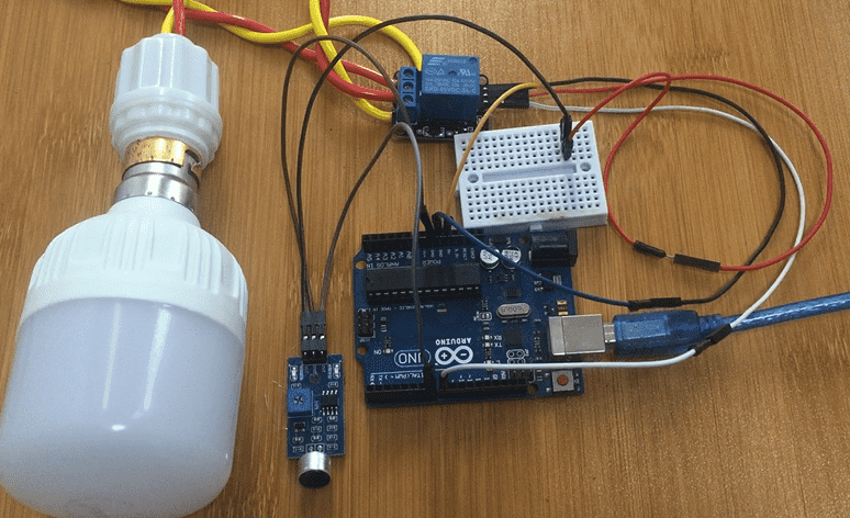
The setup is going to be as shown below. We include a single channel relay since the bulb is using a high voltage AC power supply. You can make reference to the link below to learn how the relay works:
WARNING: Be careful when dealing with High voltage sources!

Code for Clap switch using Sound sensor and Arduino.
The code is for detecting the sound of the clap which will then toggle the state of the relay and consequently turns the light on or off.
#define sensorPin 7
#define relayPin 8
// Variable to store the time when last event happened
unsigned long lastEvent = 0;
boolean relayState = false;    // Variable to store the state of relay
void setup() {
  pinMode(relayPin, OUTPUT);  // Set relay pin as an OUTPUT pin
  pinMode(sensorPin, INPUT);  // Set sensor pin as an INPUT
}
void loop() {
  // Read Sound sensor
  int sensorData = digitalRead(sensorPin);
  // If pin goes LOW, sound is detected
  if (sensorData == LOW) {
  if (millis() - lastEvent > 25) {
    relayState = !relayState;
    digitalWrite(relayPin, relayState ? HIGH : LOW);
  }
  lastEvent = millis();
  }
}
The major challenge that you may face with this setup is the sensor detecting unnecessary noise other than the clap sound. This is solved by properly adjusting the sensitivity potentiometer so the sensor can only detect sound above the required threshold.


