In this tutorial I’ll give a detailed view of the SSD1306 based I2C OLED display and how to interface it with Arduino.
What is OLED display?
OLED is short for Organic Light-Emitting Diode. These displays are made by sandwiching a series of thin organic films between two thin-film conductive electrodes. When an electric current is applied across these electrodes, the organic layers emit light.
Due to the emissive nature of OLED displays, they do not require a backlight which makes them thinner and more efficient than LCDs that require white backlight.
Advantages of OLED displays over LCDs
Compared to LCDs, OLED displays consume less power and produce better image quality with a wider color range, higher brightness, a wider angle of view and faster refresh rates.
Also, the simpler design of OLED displays makes them more durable and can be made into ultra-thin, flexible, foldable and transparent displays unlike LCDs.
The SSD1306 OLED display model.
The display that I’ll be using in this tutorial is based on the SSD1306 driver IC which is a monocolor, 0.96-inch display with 1Kb built in 128×64 bits Graphic Display Data RAM (GDDRAM). This memory is organized into 8 pages with each page having 128 segments as shown below.

Each segment also consists of 8-bits whereby each bit represents one pixel of the display. This means for the 128×64 pixel display the memory capacity will be;
8 pages x 128 segments x 8 bits of data = 8192 bits = 1024 bytes = 1KB memory
The SSD1306 OLED display modules come in different screen sizes like 128×64, 128×32, 96×16, 64×48 and 64×32. The size of the display determines the amount of RAM being used for example 128×64 OLED screen displays all the contents (8 pages) of RAM whereas 128×32 OLED screen displays only half (4 pages) of RAM.
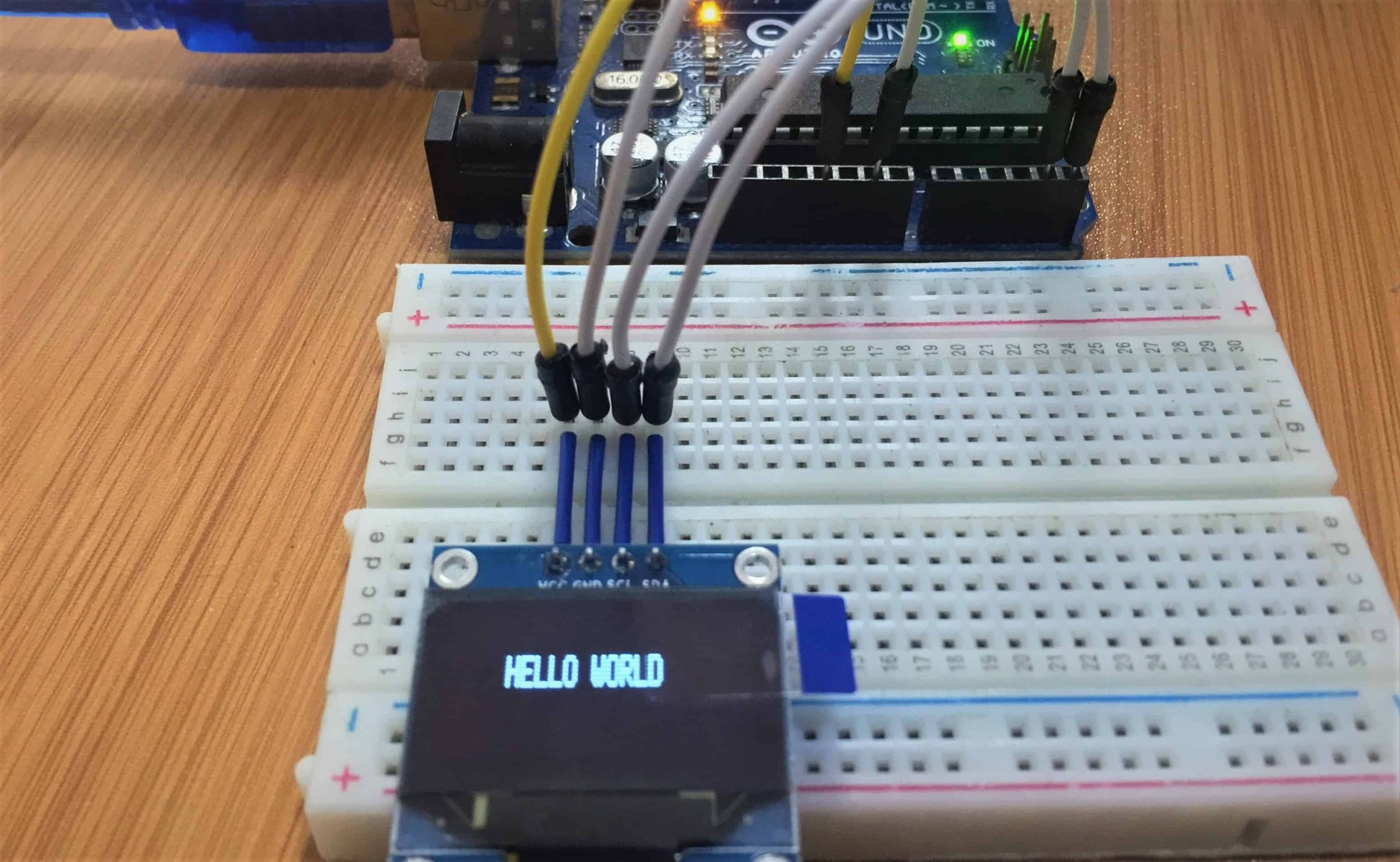
Connecting the OLED to Arduino.
An important note about I2C enabled devices is that the way you should connect them to Arduino are all the same. This is because Arduino runs its I2C communication only on specific pins. In this tutorial I’m using Arduino Uno. The Arduino Uno uses pin A5 as SCL and A4 as SDA
The pins are wired to the Arduino board as follows:
- VCC to 5V
- GND to Ground
- SCL to pin A5
- SDA to pin A4

If you’re using a different Arduino board, make sure you check the correct I2C pins for example;
- Nano: SDA (A4); SCL(A5);
- MEGA: SDA (20); SCL(21);
- Leonardo: SDA (20); SCL(21);
Getting the Address of the SSD1306 OLED Module.
Before using any I2C enabled device, you need to have the address of the module. In order to do so, after wiring up the module to your Arduino, you should just upload the I2C Scanner Code.
This code uses the Wire library which is a library included with Arduino IDE that handles I2C communication. It scans connected I2C devices and sends their address via serial port to your computer. So you can be able to see the address via Serial Monitor tool in Arduino IDE. For example in this case the address of the OLED module we are using is 0X3C.

Installing necessary Libraries.
Before writing any code for interfacing the OLED I2C display with Arduino, you need to install the “adafruit_GFX.h” and the “adafruit_SSD1306.h” libraries.
Download: Adafruit GFX library .
- Unzip the .zip folder you have downloaded and rename the Adafruit-GFX-Library-master folder to Adafruit_GFX_Library (take note of the change from “-” to “_”)
- Move the Adafruit_GFX_Library folder to your Arduino IDE installation libraries folder
Download: Adafruit_SSD1306 library.
- Unzip the .zip folder you have downloaded and rename the Adafruit-GFX-Library-master folder to Adafruit_SSD1306
- Move the Adafruit_SSD1306 folder to your Arduino IDE installation libraries folder
Finally, re-start the Arduino IDE
Code for running the OLED display using Arduino.
Some of the important functions included in the above libraries that are worth mastering if you are to know the basic use of oleds with Arduino include:
display.clearDisplay():Clears the display completelydisplay.display():Displaying data or images on the screendisplay.setCursor():to specify the coordinates of the display where we’re going to display the text.display.print():accepts the text as an string and tries to display itdisplay.write():for displaying a single character and it accepts a character code as an uint8_t type and displays the character corresponding to that code as a string.
display.setTextSize():for controlling text size.display.drawLine(startX, startY, endX, endY, color):for drawing lines.For further reference on how to use this function click here.display.drawRect(upperLeftX, upperLeftY, width, height, color):for drawing rectangles.display.drawPixel(pixelX, pixelY, color):for drawing a pointdisplay.drawBitmap():for drawing images
The code below shows the basic use of the above functions.
#include <SPI.h>
#include <Wire.h>
#include <Adafruit_GFX.h>
#include <Adafruit_SSD1306.h>
#define SCREEN_WIDTH 128 // OLED display width, in pixels
#define SCREEN_HEIGHT 32 // OLED display height, in pixels
#define OLED_RESET 4
Adafruit_SSD1306 display(SCREEN_WIDTH, SCREEN_HEIGHT, &Wire, OLED_RESET);
void setup()   {
  Serial.begin(9600);
  // by default, we'll generate the high voltage from the 3.3v line internally! (neat!)
  display.begin(SSD1306_SWITCHCAPVCC, 0x3C);  // initialize with the I2C addr 0x3C (for the 128x32)// Check your I2C address and enter it here, in Our case address is 0x3C
  display.clearDisplay();
  display.display(); // this command will display all the data which is in buffer
}
void loop() {
  display.clearDisplay();
  display.setTextSize(1);
  display.setTextColor(WHITE);
  display.setCursor(25,10);
  display.println("HELLO WORLD");
  display.display();
  delay(3000);
// drawing diagonal lines
  display.clearDisplay();
  display.drawLine(0,0,display.width() - 1, display.height() - 1, WHITE);
  display.drawLine(display.width() - 1,0,0, display.height() - 1, WHITE);
  display.display();
  delay(5000);
//drawing rectangles
  display.clearDisplay();
  display.drawRect(100, 10, 20, 20, WHITE);
  display.fillRect(10, 10, 45, 15, WHITE);
  display.drawRoundRect(60, 20, 35, 35, 8, WHITE);
  display.display();
  delay(5000);
//drawing circles
  display.clearDisplay();
  display.drawCircle(30, 15, 15, WHITE);
  display.fillCircle(25, 10, 2, WHITE);
  display.fillCircle(35, 10, 2, WHITE);
  display.display();
  delay(5000);
//drawing points
  display.clearDisplay();
  display.drawPixel(20, 35, WHITE);
  display.drawPixel(45, 12, WHITE);
  display.drawPixel(120, 59, WHITE);
  display.drawPixel(97, 20, WHITE);
  display.drawPixel(35, 36, WHITE);
  display.drawPixel(72, 19, WHITE);
  display.drawPixel(90, 7, WHITE);
  display.drawPixel(11, 29, WHITE);
  display.drawPixel(57, 42, WHITE);
  display.drawPixel(69, 34,  WHITE);
  display.drawPixel(108, 12, WHITE);
  display.display();
  delay(5000);
}
Displaying other Font types and Characters on the OLED Display.
Apart from the built-in fonts, we can also display alternative font types using the the Adafruit GFX library. You can see these fonts if you access the path to the Adafruit_GFX_Library for example in my case it is; Documents>Arduino>libraries>Adafruit_GFX_Library>Fonts

As shown above, the fonts come in various types including Mono, Serif and Sans with each of these fonts available as bold, italic, oblique and in different sizes.
- These fonts have been created with their size specified as 9px, 12px, 18px and 24px. Therefore setTextSize() method does not work when using these font types.
- The 7b in front of the font name means that the fonts are 7-bit characters.
To be able to use these fonts, you need to include the font type in your sketch, for example if I want to use FreeSerif12pt7b I’ll include the font as;
#include <Fonts/FreeSerif12pt7b.h>
The setFont() method is used to initialize the font to be used in the text displayed on the OLED. This method takes the specific font type as an argument.
For example display.setFont(&FreeSerif12pt7b); means all text after this method will use the FreeSerif12pt7b font type.
If you need to use the original fonts again, you should call the setFont() method with no arguments, that is, display.setFont();
Displaying Characters on the OLED
There are many characters that are not available in the normal fonts library for example if you want to display the degree “⁰” symbol when reading temperature. In this case we use the CodePage437 fonts which give the ASCII codes for the corresponding characters.
In the code sketch, we first set the cp437() method to true to access the CodePage437 fonts and then use the write() method having the number of the character as its argument to display the character as demonstrated in the example below.
Code for displaying alternative fonts and characters on OLED display.
#include <Wire.h>
#include <Adafruit_GFX.h>
#include <Adafruit_SSD1306.h>
#include <Fonts/FreeSerifBold9pt7b.h>

#define SCREEN_WIDTH 128 // OLED display width, in pixels
#define SCREEN_HEIGHT 32 // OLED display height, in pixels
#define OLED_RESET -1

Adafruit_SSD1306 display(SCREEN_WIDTH, SCREEN_HEIGHT, &Wire, OLED_RESET);

void setup() {
  Serial.begin(115200);

  if(!display.begin(SSD1306_SWITCHCAPVCC, 0x3C)) {
    Serial.println("SSD1306 allocation failed");
    for(;;);
  }
  delay(2000);

  display.setFont(&FreeSerifBold9pt7b);
  display.clearDisplay();
  display.setTextColor(WHITE);
  display.setCursor(15,12);
  display.println("HELLO");
  display.display();
  display.setFont();

  display.setTextSize(1);
  display.setTextColor(WHITE);
  display.setCursor(10,20);
  display.cp437(true);
  display.write(35);
  display.print(" ");
  display.write(42);
  display.print(" ");
  display.write(175);
  display.print(" ");
  display.write(156);
  display.print(" ");
  display.write(36);
  display.setCursor(80,15);
  display.cp437(true);
  display.write(167);
  display.setTextSize(2);
  display.print("C");

  display.display();
  delay(2000);
}
void loop() {
}
When this code is uploaded to the Arduino, the word “HELLO ” in Serif Bold font type and various characters will be displayed on the OLED display as shown below;

Displaying Bitmap Images on the OLED.
The SSD1306 OLED display is monocolor (black and white) therefore images to be shown on the display have to first be converted to a supported format which is monochrome bitmap.
You can use any image editing software like Photoshop, Inkscape and others to resize to the display dimensions and convert the image to monochrome bitmap (bmp) format. I will show you how I did this using Paint on my Windows computer.
First Open the image using Paint and go to Home>Resize as shown below.
- Select Resize by Pixels and uncheck Maintain aspect ratio.
- Fill in the dimensions of the display you are using for example in my case it is 128×32 pixels.
- Press OK and the image will be resized to the required display dimensions.

- Then save the image as a Monochrome bitmap picture by going to File> Save as > BMP picture
- Select the file where the image is to be saved and under Save as type choose Monochrome Bitmap.

Converting the Bitmap image to an array.
After creating the bitmap image, we need to convert it to a byte array so that we can be able to include it in our code sketch.
There are a number of tools available for converting images to byte arrays but I have used the image2cpp tool.
With this tool you can upload the image you want to convert to a byte array, set the dimensions and other properties as shown below.

Then you can have a preview of how the image will appear on the OLED and go ahead to generate the code array to use for displaying the image.

Code for displaying Bitmap image on OLED using Arduino.
#include <Wire.h>
#include <Adafruit_GFX.h>
#include <Adafruit_SSD1306.h>

#define SCREEN_WIDTH 128
#define SCREEN_HEIGHT 32
#define OLED_RESET -1

Adafruit_SSD1306 display(SCREEN_WIDTH, SCREEN_HEIGHT, &Wire, OLED_RESET);

// Bitmap Image
const unsigned char Arduino_logo [] PROGMEM = {
 0xff, 0xff, 0xff, 0x80, 0x07, 0xff, 0xff, 0xff, 0xff, 0xff, 0xff, 0x80, 0x03, 0xff, 0xff, 0xff,
 0xff, 0xff, 0x00, 0x00, 0x00, 0x03, 0xff, 0xff, 0xff, 0xff, 0x80, 0x00, 0x00, 0x03, 0xff, 0xaf,
  0xff, 0xf0, 0x00, 0x00, 0x00, 0x00, 0x1f, 0xff, 0xff, 0xf8, 0x00, 0x00, 0x00, 0x00, 0x1f, 0xff,
  0xff, 0x80, 0x00, 0x00, 0x00, 0x00, 0x03, 0xff, 0xff, 0x80, 0x00, 0x00, 0x00, 0x00, 0x01, 0xff,
  0xfe, 0x00, 0x07, 0xff, 0xff, 0xc0, 0x00, 0x7f, 0xfe, 0x00, 0x07, 0xff, 0xff, 0xc0, 0x00, 0x7f,
  0xf8, 0x00, 0x7f, 0xff, 0xff, 0xfc, 0x00, 0x0f, 0xf0, 0x00, 0x3f, 0xff, 0xff, 0xfc, 0x00, 0x1f,
  0xe0, 0x01, 0xff, 0xff, 0xff, 0xff, 0x80, 0x03, 0xc0, 0x01, 0xff, 0xff, 0xff, 0xff, 0x80, 0x07,
  0xc0, 0x07, 0xff, 0xff, 0xff, 0xff, 0xf0, 0x00, 0x00, 0x0f, 0xff, 0xff, 0xff, 0xff, 0xe0, 0x03,
  0x80, 0x0f, 0xff, 0xff, 0xff, 0xff, 0xfc, 0x00, 0x00, 0x3f, 0xff, 0xf0, 0x3f, 0xff, 0xf0, 0x01,
  0x00, 0x1f, 0xff, 0xff, 0xff, 0xff, 0xff, 0x00, 0x00, 0xff, 0xff, 0xf0, 0x3f, 0xff, 0xf8, 0x01,
  0x00, 0x3f, 0xf8, 0x00, 0x00, 0x3f, 0xff, 0xc0, 0x03, 0xff, 0xfe, 0x00, 0x00, 0xff, 0xfc, 0x00,
  0x00, 0x3f, 0xff, 0xff, 0xff, 0xff, 0xff, 0x80, 0x03, 0xff, 0xfe, 0x00, 0x00, 0xff, 0xfc, 0x00,
  0x00, 0x3f, 0xff, 0xff, 0xff, 0xff, 0xfe, 0x00, 0x00, 0xff, 0xff, 0xf8, 0x3f, 0xff, 0xf8, 0x01,
  0x80, 0x1f, 0xff, 0xff, 0xff, 0xff, 0xfc, 0x00, 0x00, 0x3f, 0xff, 0xf0, 0x3f, 0xff, 0xf0, 0x01,
  0x80, 0x0f, 0xff, 0xff, 0xff, 0xff, 0xf0, 0x00, 0x00, 0x0f, 0xff, 0xff, 0xff, 0xff, 0xe0, 0x03,
  0xc0, 0x03, 0xff, 0xff, 0xff, 0xff, 0x80, 0x03, 0xc0, 0x03, 0xff, 0xff, 0xff, 0xff, 0x80, 0x07,
  0xf0, 0x00, 0xff, 0xff, 0xff, 0xfe, 0x00, 0x0f, 0xf0, 0x00, 0x7f, 0xff, 0xff, 0xfe, 0x00, 0x1f,
  0xfc, 0x00, 0x0f, 0xff, 0xff, 0xe0, 0x00, 0x7f, 0xfc, 0x00, 0x07, 0xff, 0xff, 0xe0, 0x00, 0x7f,
  0xff, 0x00, 0x00, 0x0f, 0xf0, 0x00, 0x01, 0xff, 0xff, 0x80, 0x00, 0x0f, 0xfc, 0x00, 0x01, 0xff,
  0xff, 0xf0, 0x00, 0x00, 0x00, 0x00, 0x0f, 0xff, 0xff, 0xf0, 0x00, 0x00, 0x00, 0x00, 0x0f, 0xff,
  0xff, 0xff, 0x00, 0x00, 0x00, 0x00, 0xff, 0xff, 0xff, 0xff, 0x00, 0x00, 0x00, 0x00, 0xff, 0xff,
  0xff, 0xff, 0xfe, 0x00, 0x00, 0x7f, 0xff, 0xff, 0xff, 0xff, 0xfe, 0x00, 0x00, 0x3f, 0xff, 0xff,
  0xff, 0xff, 0xff, 0xff, 0xff, 0xff, 0xff, 0xff, 0xff, 0xff, 0xff, 0xff, 0xff, 0xff, 0xff, 0xff,
  0xff, 0xff, 0xff, 0xff, 0xff, 0xff, 0xff, 0xff, 0xff, 0xff, 0xff, 0xff, 0xff, 0xff, 0xff, 0xff,
  0xfe, 0x07, 0xfc, 0x00, 0xfe, 0x00, 0x7f, 0x87, 0xf8, 0xf0, 0x00, 0x7c, 0x1f, 0x8f, 0xe0, 0x1f,
  0xfe, 0x03, 0xfc, 0x7e, 0x1e, 0x1f, 0x87, 0x87, 0xf8, 0xff, 0x8f, 0xfc, 0x0f, 0x8f, 0x0f, 0xc3,
  0xfc, 0x61, 0xfc, 0x7e, 0x1e, 0x1f, 0xc3, 0x87, 0xf8, 0xff, 0x8f, 0xfc, 0x47, 0x8e, 0x1f, 0xe1,
  0xf8, 0x70, 0xfc, 0x38, 0x7e, 0x1f, 0xe3, 0x87, 0xf8, 0xff, 0x8f, 0xfc, 0x63, 0x8e, 0x1f, 0xe1,
  0xf0, 0xf8, 0x7c, 0x31, 0xfe, 0x1f, 0xc3, 0x87, 0xf8, 0xff, 0x8f, 0xfc, 0x71, 0x8e, 0x1f, 0xe1,
  0xe0, 0x00, 0x7c, 0x7c, 0x3e, 0x1f, 0xc3, 0xc7, 0xf8, 0xff, 0x8f, 0xfc, 0x78, 0x0e, 0x1f, 0xe1,
  0xe3, 0xfc, 0x3c, 0x7e, 0x1e, 0x1e, 0x0f, 0xc3, 0xe1, 0xff, 0x87, 0xfc, 0x7c, 0x0f, 0x87, 0x87,
  0xff, 0xff, 0xff, 0xff, 0xef, 0xff, 0xff, 0xfe, 0x1f, 0xff, 0xff, 0xff, 0xff, 0xff, 0xf8, 0xff
};

void setup()
{
  Serial.begin(115200);

  // initialize with the I2C addr 0x3C
  if(!display.begin(SSD1306_SWITCHCAPVCC, 0x3C)) {
    Serial.println(F("SSD1306 allocation failed"));
    for(;;);
  }
  delay(2000); // Pause for 2 seconds

  // Clear the buffer.
  display.clearDisplay();

  // Display bitmap image
  display.drawBitmap(0, 0, Arduino_logo, 128, 32, WHITE);
  display.display();

}

void loop() {
 }
The drawBitmap() method is used to display the array.
This method takes the arguments (x, y, image array, image width, image height, rotation). The (x, y) coordinates define where the image starts to be displayed.
When this code is uploaded to the OLED, a monocolor image will be displayed as shown below.

I have used this display in a number of other projects which you can check out for further practice on how to use the 12C OLED display with other sensors and Arduino;
- Digital Clock using DS3231 RTC, OLED and Arduino
- DHT11 Temperature and Humidity sensor with OLED and Arduino
- MLX90614 Non-Contact Infrared Temperature Sensor with Arduino and OLED.


