INTERFACING SWITCHES WITH ARDUINO.(INTERNAL PULL-UP RESISTORS.)
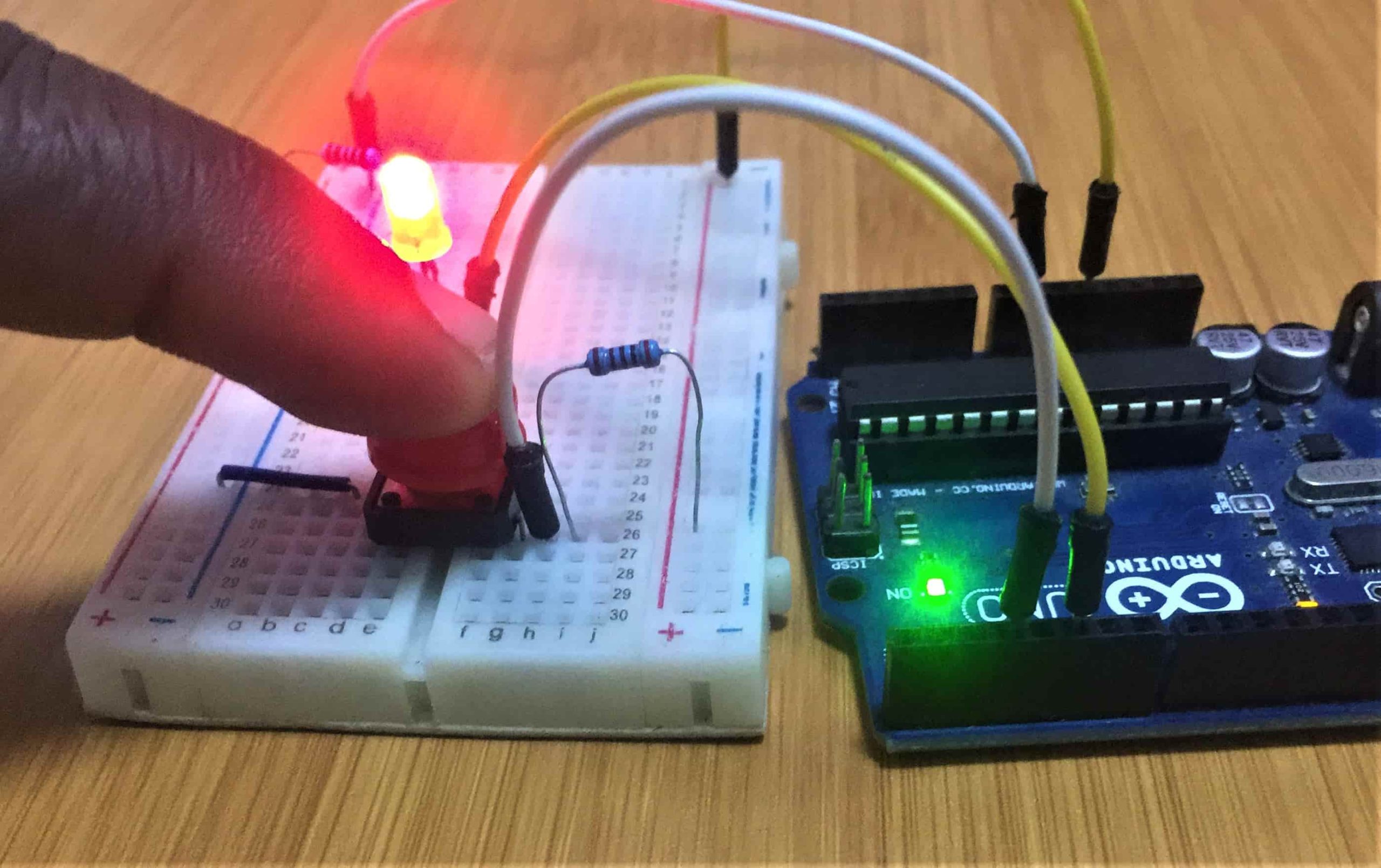
Among the most common challenges beginners find when using switches with microcontrollers like Arduino is the “floating pin” or “floating input”. To explain this phenomenon lets consider a simple connection used to turn an led on and off using a push button switch as shown below.
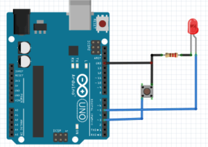
The Led is connected to Arduino pin 5 and the push button is connected to pin 3.
The code below is uploaded to the board. From the code the pin 3 is declared as INPUT without a pullup resistor.
void setup() {
  pinMode(3,INPUT);   //push button
  pinMode(5,OUTPUT); // led
  Serial.begin(9600);
}
void loop() {
  int pushButton = digitalRead(3);
  Serial.println(pushButton);
  if(pushButton == HIGH)
  {
    digitalWrite(5, LOW);
  }else{
    digitalWrite(5, HIGH);
  }
delay(500);
}
This code is supposed to turn the state of pin 5 HIGH when the button is pressed so the led will turn on and when the push button is not pressed the pin 5 will turn LOW and the led will be off.
However when the switch is not being pressed it enters a state of “Floating”. which is when the Arduino digital pin is neither HIGH nor LOW and results in noise. This makes the Led lighting irregular, sometimes it turns on and at times it’s off regardless of the state of the switch.
Using Pull-up resistor to solve the Floating input problem.
To fix the floating pin problem above we connect the push button switch pin that is connected to the Arduino Digital pin 5 to either Ground or 5V depending on what we are trying to read when the switch is pressed.

We want to read LOW when the switch is pressed so we have to connect the switch to 5V, which will result in the switch being “pulled up” when the switch is not being pressed and the Arduino would read the Digital pin HIGH without any noise. Here the pin is Pulled Up to 5V when the switch is not being pressed.
We can not just go ahead and connect pin 3 directly to Ground or 5V since that would create a short circuit when the switch is pressed, this is why we need to use a Resistor. The Resistor prevents the short circuit by limiting the amount of current to flow when the switch is pressed. You can use any resistor in the range 1k to 50k.
Pull-up means that the pushbutton’s logic is inverted. It goes HIGH when it’s open and LOW when pressed. Turn on the LED when the button is pressed and off when it’s not.
Using Arduino internal Pull-up Resistors.
The Arduino UNO has in-built pull-up resistors of about 20k to 50k available on each one of the Digital Pins. These resistors can be activated or deactivated at will inside the code.
This reduces cluttering your board up with pull-up resistors of your own for all the buttons and other components which gives your design much more flexibility.
The floating pin problem from the example used above can be solved without including external pull-up resistors on pin 3. We simply activate the internal pull-up resistor of pin 3 by changing the part of code to declare pin as: pinMode(3,INPUT_PULLUP)
void setup() {
  //pull-up resistor
  pinMode(3,INPUT_PULLUP);
  pinMode(5,OUTPUT); // led
  Serial.begin(9600);
}
void loop() {
  int pushButton = digitalRead(3);
  Serial.println(pushButton);
  if(pushButton == HIGH)
  {
    digitalWrite(5, LOW);
  }else{
    digitalWrite(5, HIGH);
  }
delay(500);
}
Hope this can clarify on the idea of floating inputs and the use of internal pull up resistors when interfacing switches with Arduino. I have done a number of projects with switches which you can refer to:

