SIM900 GSM/GPRS Shield with Arduino.
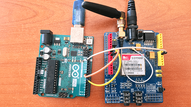
SIM900 GSM/GPRS module can be used in a number of projects involving wireless communication using cellphone functions like sending and receiving SMS and calls for example controlling home appliances using SMS. In this tutorial am going to show you how the SIM900 GSM/GPRS shield can be interfaced with Arduino.
SIM900 GSM/GPRS Shield Hardware Overview
This shield is based on the SIM900 module from SIMCOM enabling you send and receive SMS text messages, make or receive phone calls and connecting to internet through GPRS just like any normal cell phone. The shield is configured and controlled via its UART using AT commands and supports quad-band GSM/GPRS network of 850, 900, 1800 and 1900 MHZ, therefore can work in all countries with GSM (2G) networks.
The diagram below shows the main parts of the SIM900 GSM/GPRS shield.
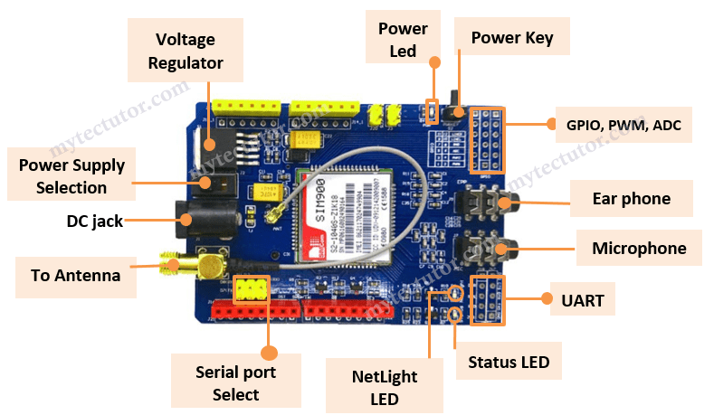
- Indicator LEDs -The PWR LED turns on when the shield is powered,
Status LED indicates that the chip is in working mode
Netlight LED indicates the status of your cellular network. It’ll blink at various rates to show what state it’s in for example the NetLight LED will blink every 800 ms until the SIM900 chip finds a network and when it finds the network, the NetLight LED will start blinking every three seconds. - Speaker and microphone – for using the SIM900’s audio interface to make and receive voice calls and listen FM radio.
- Antenna – There are U.FL and SMA antenna connectors connected through a patch cord and a 3dBi GSM antenna for improved voice and data communications even when the shield is inside a casing.
- UART ports – the shield uses UART protocol to communicate with microcontrollers like Arduino supporting baud rates from 1200bps to 115200bps with Auto-Baud detection.
- Serial port selection jumpers – these are placed depending on whether you want to connect (RX,TX) of the shield to either Software Serial(D8,D7) or Hardware Serial(D1,D0) of the Arduino.
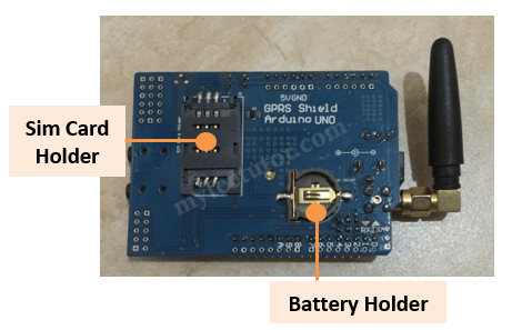
At the backside of the shield there is a SIM card socket where you can place an activated 2G SIM card and a battery holder for a CR1220 battery for the internal Real Time Clock (RTC).
Power supply considerations for the SIM900 GSM/GPRS Shield
The SIM900 chip has a maximum current draw of 2A and an operating voltage of 3.4V to 4.4V. The shield comes with a high current, high accuracy, low-dropout MIC29302WU voltage regulator capable of handling load currents up to 3A. This keeps the supply voltage safe at 4.1V.
You can use an external power supply through the 5.5mm DC jack. Next to the power jack there is a toggle switch with an arrow pointing to the “EXTERN” label. To use an external power source, move the toggle switch in the direction of the arrow to select the external power source.
It is advisable to use a 5V power supply that can provide 2A to avoid having the chip shutting down. It can also be powered with 9V 1A, or 12V 1A.
Testing the SIM900 GSM/GPRS Shield.
To test whether your SIM900 shield is working properly, we can use AT commands to communicate with the SIM900 shield via the serial monitor of Arduino IDE.
First you need to connect the SIM900 shield directly to a PC using any USB to TTL converter for example the FT232RL FTDI USB to TTL converter as shown below.
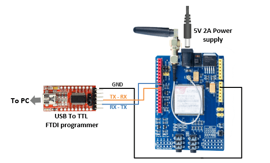
Before using the above USB to TTL converter you should have the correct drivers installed on your PC otherwise it will not work. You can also check out my other tutorial on how to install FTDI drivers for the FT232RL USB to TTL serial adapter module.
After making the above connections, open the Arduino IDE and select the right COM port. Then open the Serial monitor and Select 19200 baud rate and Carriage return.
Now you can begin writing various AT commands in the serial monitor and press enter to see the result. The first command is AT which is the most basic AT command. If the shield works fine you should see the AT characters in the serial monitor and then OK, meaning the shield is communicating correctly!
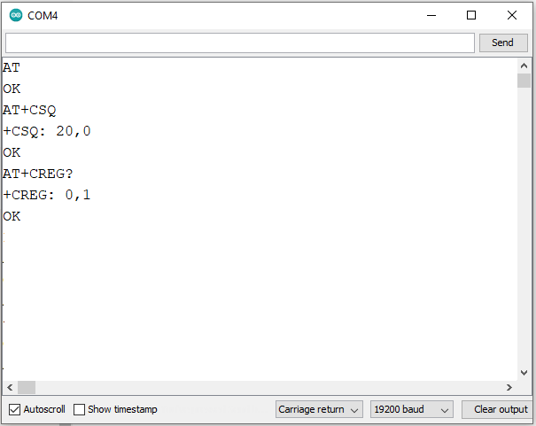
You can then send other commands to the shield and get information about it for example;
- AT+CSQ – checks the ‘signal strength’ as shown by the first value in the range 0 to 31. A good signal should be higher than 5.
- AT+CCID – for getting the SIM card number
- AT+CREG? – checking whether the module is registered on the network. The second number can be 1 for indicating that you are registered to home network ,5 indicates roaming network and any other value apart from these two indicates not registered to any network.
- AT+COPS=? – gives the list of network operators present
Connecting SIM900 GSM/GPRS Shield to Arduino UNO
The connection is done as shown below with D7(Tx) and D8(Rx) pins on shield connected to digital pin7 and 8 of Arduino respectively.
We are going to use software serial to communicate with the shield, therefore the Serial port selection jumper caps should placed on the software serial port select position.
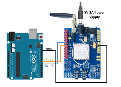
The shield is powered by an external power supply rated 5V 2A and don’t forget to move the toggle switch next to the DC jack to select the external power source.
Connect the ground, connect the antenna and insert a fully activated SIM card in the socket at the back of the shield.
Powering the SIM900 Shield up or down.
Powering the SIM900 chip can be done in two ways;
Hardware Trigger
This involves manually pressing for about 2 seconds the tactile switch labelled PWRKEY near the PWR LED indicator in order to power the SIM900 chip up or down.
Software trigger
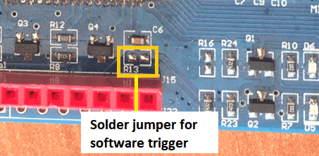
This involves turning the SIM900 chip up/down programmatically. To do this you need to first solder the SMD jumper labelled R13 on the shield shown in the image below.
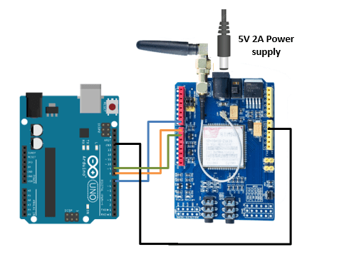
Then, you need to connect D9 pin on the shield to the D9 pin on Arduino.
And finally, you need to add the following function in your code sketch.
void SIM900power()
{
  pinMode(9, OUTPUT);
  digitalWrite(9,LOW);
  delay(1000);
  digitalWrite(9,HIGH);
  delay(2000);
  digitalWrite(9,LOW);
  delay(3000);
}
Code for sending SMS using SIM900 module and Arduino.
To send SMS messages from the SIM900 shield you need to upload the code sketch below to your Arduino.
#include <SoftwareSerial.h>

SoftwareSerial SIM900(7, 8);

void setup() {
  SIM900.begin(19200);
  delay(20000);
  sendSMS();
}

void loop() {

}

void sendSMS() {
  SIM900.print("AT+CMGF=1\r");
  delay(100);
  SIM900.println("AT+CMGS=\"+XXXXXXXXXXXX\"");
  delay(100);
  SIM900.println("Write the message you want to send");
  delay(100);

  // End AT command with a ^Z, ASCII code 26
  SIM900.println((char)26);
  delay(100);
  SIM900.println();
  delay(5000);
}
First include the SoftwareSerial.h library and create a software serial object with arguments of the Arduino pins to which Tx and Rx of SIM900 shield is connected, that is, Pin 7 is being set as Rx and 8 as Tx.
In the setup() section, we initialize a serial communication link between Arduino and SIM900 shield at a baud rate of 19200.
The sendSMS() function is the one that actually sends the SMS using the AT commands:
- AT+CMGF=1\r – for selecting SMS message format as text.
- AT + CMGS=\”+xxxxxxxxxxxxx””\ – for sending SMS to the phone number specified. Replace the Xs with your recipient mobile number in international format.
To specify the text message you want to send as SMS, you to end the AT command with ASCII code 26 which is ^Z.
The loop() section is kept empty since we want to send SMS only once.
Code for reading received SMS using SIM900 module and Arduino.
The code below should be uploaded to Arduino to read incoming messages. After uploading, wait 20 seconds for the shield to establish communication. Then, test the script by sending an SMS to the shield SIM card number.
#include <SoftwareSerial.h>
SoftwareSerial SIM900(7, 8);
//Variable to save incoming SMS characters
char incoming_char=0;

void setup() {
  SIM900.begin(19200);
  Serial.begin(19200);
  delay(20000);

  SIM900.print("AT+CMGF=1\r");
  delay(100);
  SIM900.print("AT+CNMI=2,2,0,0,0\r");
  delay(100);
}

void loop() {
  if(SIM900.available() >0) {
    incoming_char=SIM900.read();
    Serial.print(incoming_char);
  }
}
The sketch is similar as earlier except below code snippet. Once the connection is established, we send below AT commands:
- AT+CMGF=1 – selects SMS message format as text.
- AT+CNMI=1,2,0,0,0 – specifies how newly arrived SMS messages should be handled. This way you can tell the SIM900 shield either to forward newly arrived SMS messages directly to the PC, or to save them in message storage and then notify the PC about their locations in message storage.
The incoming characters from the SMS message are stored in the incoming_char variable and read using the SIM900.read() method.
In this case the loop() section is not empty because you need to keep polling for newly arrived SMS messages.
The SMS messages you send to SIM900 GSM/GPRS shield will be seen in the serial monitor.
Code for making a phone call using SIM900 module and Arduino.
The code sketch below is used to make a phone call. Don’t forget to connect a microphone and earphones to make the call.
#include <SoftwareSerial.h>
SoftwareSerial SIM900(7, 8);

void setup() {
  SIM900.begin(19200);
  delay(20000);
  callSomeone();
}

void loop() {

}

void callSomeone() {
  SIM900.println("ATD + +XXXXXXXXX;");
  delay(100);
  SIM900.println();

  delay(30000);
  SIM900.println("ATH"); // hang up
}
To place a call you use the callSomeone() function that uses the following AT commands:
- ATD+ +xxxxxxxxxxxx; – Dials a specified number. The semicolon
;modifier at the end separates the dial string into multiple dial commands. All but the last command must end with the semicolon;modifier. - ATH – Hangs up the call and is very useful in triggering events.
Code for answering incoming phone calls using SIM900 module and Arduino.
To receive incoming calls, you need to just keep listening to the SIM900 shield so that when someone calls the SIM900 number, it sends a message saying “RING”. The code below is for reading the incoming characters from the SIM900 and then, compare if it was a RING message.
When it receives a RING message, you send the ATA command to answer the phone.
#include <SoftwareSerial.h>
SoftwareSerial SIM900(7, 8);
char incoming_char=0;

void setup() {
  SIM900.begin(19200);
  Serial.begin(19200);
  delay(20000);

  SIM900.print("AT+CLIP=1\r"); // turn on caller ID notification
  delay(100);
}

void loop() {
  if(SIM900.available() >0) {
    incoming_char=SIM900.read();
    if (incoming_char=='R') {
      delay(10);
      Serial.print(incoming_char);
      incoming_char=SIM900.read();
      if (incoming_char =='I') {
        delay(10);
        Serial.print(incoming_char);
        incoming_char=SIM900.read();
        if (incoming_char=='N') {
          delay(10);
          Serial.print(incoming_char);
          incoming_char=SIM900.read();
          if (incoming_char=='G') {
            delay(10);
            Serial.print(incoming_char);
            SIM900.print("ATA\r");
          }
        }
      }
    }
  }
}
An incoming call is usually indicated by ‘RING’ on serial monitor followed by phone number and caller ID. To accept/hang a call following AT commands are used:
- ATA – Accepts incoming call.
- ATH – Hangs up the call. On hanging up the call it sends NO CARRIER on the serial monitor indicating call couldn’t connect.

