Arduino PWM output is essential in a number of applications for example in controlling the brightness of a light bulb or controlling the speed of rotation of motors. PWM stands for Pulse Width Modulation and it enables the Arduino to output analog signals using its digital outputs.
Why do we need Arduino PWM Output signals?
An analog signal is a continuous signal, that is, it can take on any number as a value unlike a digital signal that has only two values, HIGH and LOW. If you want to control a LED with a digital signal then it can either be “off” when the signal is LOW or “on” when the signal is HIGH. For the Arduino LOW signal is 0V and HIGH is 5V.
The challenge comes when for example you want the LED to be half bright. Then you either have to reduce the current across the LED into half or use the PWM technique so as to send a 50% duty cycle square wave signal to the LED.
The analogRead() function
Arduino has an in built 10 bit analog-to-digital converter (ADC) that turns analog voltage to digital signals. When writing code the analogRead() function is used to obtain the value of the analog signal.
This function converts the value of the voltage on a given analog pin to a digital value from 0 to 1023 in comparison to a reference voltage 5V or 3.3V. This means that 0 corresponds to a voltage of 0V and 1023 is for 5V or 3.3v. The analogRead() function takes only one argument which is the pin number for reading the analog voltage.
What is a PWM signal?
A PWM signal is a periodic rectangular signal of fixed frequency that can be approximated to analog voltage levels by changing its duty cycle. The maximum analog voltage that such a signal can approximate is the amplitude of the rectangular wave. A simple demonstration of pwm signal waveforms is shown in the diagram below.

From the wave forms above we can conclude that the duty cycle describes the proportion of time the power is on for a given period of time. Duty cycle is expressed as a percentage, for example when the duty cycle is 100%, the pwm signal approximates to 5V.
When a digital signal is on half of the time and off the other half of the time, the digital signal has a duty cycle of 50% and resembles a “square” wave and the PWM signal approximates to 2.5V.
Generating PWM signals using Arduino.
Among the major downsides of most Arduino boards is the lack of an in built digital-to-analog converter (DAC) therefore they cannot provide true analog signals. However, majority of these boards can output a pulse-width modulated digital signal that can be approximated to the analog voltage levels.
In Arduino the duty cycle of a pwm signal is controlled by an 8-bit register and therefore we can have 256 voltage levels between 0 and 5V. These voltage levels differ by 19.6 mV (5V/255) from the adjacent voltage levels.
The voltage levels are from 0 to 255 where 0 signifies a 0% duty cycle and a value of 255 signifies a 100% duty cycle. We can obtain other duty cycles using intermediate values, such as 64 for a 25% duty cycle, 127 for a 50% duty cycle, 191 for a 75% duty cycle.
Not all pins of the Arduino support PWM signals. The PWM pins are marked by the tilde sign (~). Most Arduino boards have six PWM pins 3, 5, 6,9,10 and 11. Pins 5 and 6 generate a PWM signals at 980 Hz frequency and other pwm pins use a frequency of 490 Hz frequency. To generate a pwm signal from these pins we use the analogWrite() function.
The frequency of the PWM signal does not have any impact on the number of voltage levels that can be achieved by the signal. The higher the frequency of the PWM signals, the better the precision of the voltage level.
The analogWrite() function.
This function is used to generate a pwm signal at a given pin. The syntax is analogWrite(pin, value). It requires two arguments which are the pin number where the pwm signal is to be generated and a value for the duty cycle (0 to 255).
When using analogWrite() function there is no need for using the pinMode() function to set up the pins being used as outputs. This is because the pinMode() function is called inside the body of the analogWrite() function.
Adjusting brightness of an LED using Arduino PWM Output.
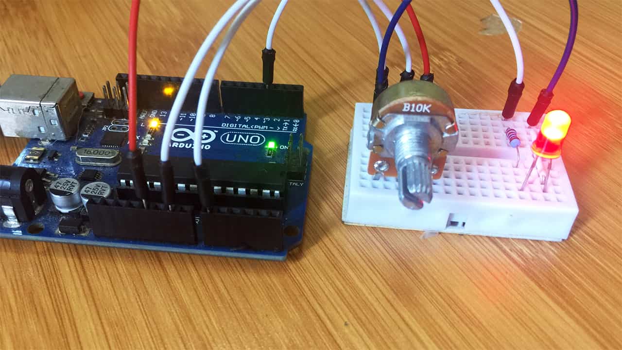
A simple application of pwm signals is the control of brightness of LEDs. In this example I’ll connect an LED to pin 3 and will be able to control its brightness using a potentiometer that is connected to analog pin A0. The setup is as shown below. The LED can be connected to any PWM enabled pin.

Code for controlling brightness of the LED.
const int ledPin = 3 ;
const int pot = 0 ;

void setup(){
     Serial.begin(9600);
     pinMode(ledPin,OUTPUT) ;        //setting pin 2 as output
}

void loop(){

     int pot  = analogRead(0) ;
     pot = map(pot, 0, 1023, 0, 255);
     int dutyCycle = map(pot,0, 255, 0, 100);
     analogWrite(ledPin,pot) ;
     Serial.print(dutyCycle);
     Serial.println(" %");
     delay(2000);
}
The analogRead() function is used to convert the value of the voltage on analog pin A0 to a digital value from 0 to 1023. These values are changed by rotating the potentiometer.
A map() function is then used to change the analog voltage levels from 0 to 1023 to pwm signal voltage levels of 0 to 255. These PWM signals are then used to control the voltage levels on pin 3 using the analogWrite() which in turn control the level of brightness of the LED.
Another map() is for converting the PWM voltage levels to the corresponding duty cycle as a percentage. This value can be observed on the serial monitor.
After uploading this code to the Arduino, when the potentiometer is rotated, the duty cycle of the PWM signal on digital pin 3 is changed which results in adjustment of brightness of the LED.

Arduino PWM outputs are used in a number of applications for example in the control of servo motors using the PCA9685 16-Channel 12-bit servo motor driver.


