How to Use a Digital Multimeter.
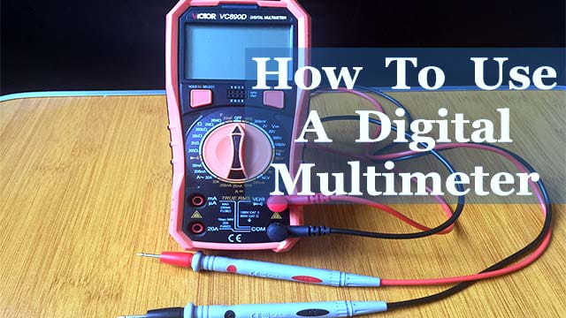
Knowing how to use a digital multimeter is one of the essential skills needed when dealing with electronics. A multimeter is used for testing, diagnosing, and troubleshooting electrical circuits, components and devices. It’s mainly used for measuring voltage, resistance and current.
Digital multimeters come in various shapes from different manufacturers and can have a number of functionalities but for this tutorial I will look at the primary applications of any multimeter that you may want to buy.
Parts of a multimeter
Modern digital multimeters have four parts:
- LCD Display with multiple digits for showing the various parameters being measured.
- Range Selector Dial for selecting the function to be used and the range of measurements being taken.
- Connection Ports: These are 4mm diameter female sockets into which 4 mm probe leads are plugged. Their arrangement varies depending on the model of the meter. However, you need to know the function of each socket so that so don’t damage your multimeter.
- COM port is kind of standard for all multimeters and is the common socket where the black probe lead is plugged.
- VΩmA port indicates that when the red probe lead is plugged into it, the multimeter can measure voltage “V”, resistance “Ω” or low current “mA”. In other multimeters, it is labelled VΩ and there will be one or more separate sockets for connecting the red probe lead to measure current. These sockets will be marked “A” or “mA” with the maximum current range. For example, in my case it is 20A for high current readings and 200 mA for lower current readings.
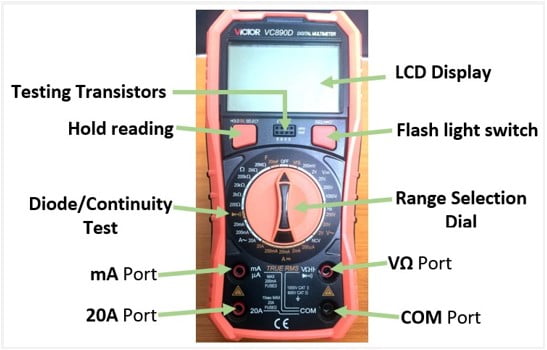
- Probes which are insulated wires with pointed tips on one end for placing at the point of measurement and a plug on the other end for insertion into the connection ports. Alternatively, crocodile probes can also be used especially in situations where the probes are to be connected to a circuit without holding them by hand. These probes usually come as a pair with one black and another red.
What do the symbols on a Multimeter Dial mean?
Below are some of the common symbols you will find used on most multimeters and their meanings.
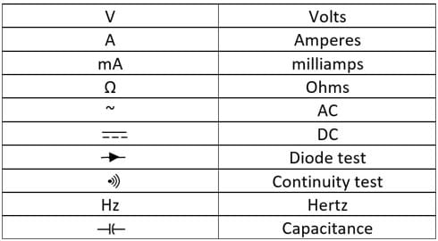
Depending on the multimeter model in use you can find other labels and symbols corresponding with the additional functionalities for example in the Victor VC8900 model above there are symbols for measuring capacitance in Farads (F), DC current gain of a transistor (hFE) and non-contact voltage (NCV).
Using a digital multimeter to measure Voltage.
Voltage can be either DC for example from a battery or AC like a home wall socket power point.
To measure voltage, the black probe is inserted in the COM port and the red probe into the VΩ port.
Measuring DC voltage
Connect the black probe to the battery’s negative terminal and the red probe to the positive terminal.
Turn the dial to DC voltage range and if you are not certain of the voltage range to choose, always begin with a higher voltage.
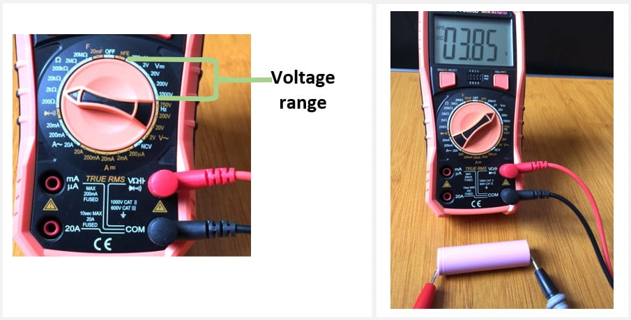
Most modern digital multimeters automatically detect polarity therefore when taking DC voltage measurements and the probes are touching opposite terminals, a negative symbol will appear in the display.
Measuring AC voltage.
Unlike DC voltage, AC voltage does not have polarity so the probes can touch any terminal of the voltage source.
Turn the dial to AC voltage range and begin with the highest voltage value.
Measuring Resistance using a digital multimeter.
1.First turn off the power in the circuit and if possible, measure the component resistance separately.
2.Insert the black probe lead into COM port and the red one into the port with Ω symbol.
3.Turn the dial to Resistance range and set the highest range available.
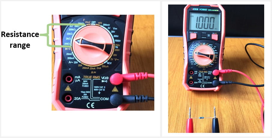
4. Place the probe leads at either ends of the component being measured and observe the reading on the display. You can adjust the dial to get more accurate readings.
Measuring Continuity using a digital multimeter
This is one of the most common use of a multimeter and it helps to test the flow of electricity from one point in a circuit to another. It is useful for checking for circuit breaks in various electrical appliances, blown fuses and tracing PCB tracks.
1.Turn off the power in the circuit being tested.
2.Insert the black probe into COM port and the red probe into the continuity port. Turn the selection dial to the continuity symbol as shown below.
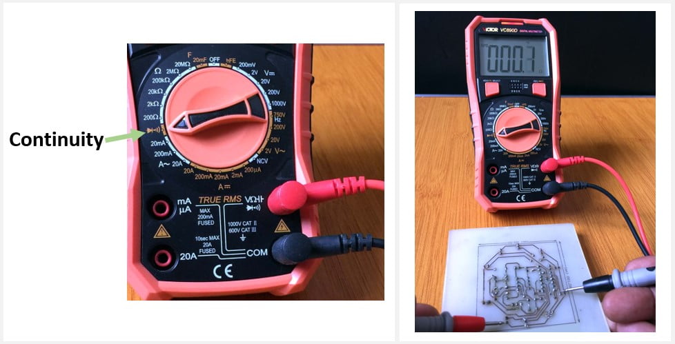
Normally when the dial is set to ‘resistance’ or ‘continuity’ mode and no testing is being done, the digital multimeter will display a non-numerical indication on the display like “OL” (Open-Loop) and other models display dashed lines.
3.Place the tips of each probe at either ends of the conductor or fuse which needs to be checked. The multimeter then sends a tiny current between the two points being checked.
If the points are intact, the multimeter will give a beeping sound and display a tiny reading. If there is no continuity no beep is produced and usually the digit “1”, will be displayed.
How to use a digital multimeter to measure Current.
1. First turn off the power in the circuit and connect the probe leads such that the black probe lead is inserted into the COM port and the red probe into either the mA port for low current or 10A or 20A port for high current measurements.
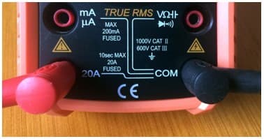
The mA port is normally marked with the maximum current it can withstand and since you may not be sure that the current you are measuring is less or greater than this value, it is advisable to begin by using the 10A or 20A port to avoid blowing a fuse in the meter.
2.To measure current the multimeter must be placed in series with the circuit, that is, it is part of the circuit as illustrated below.
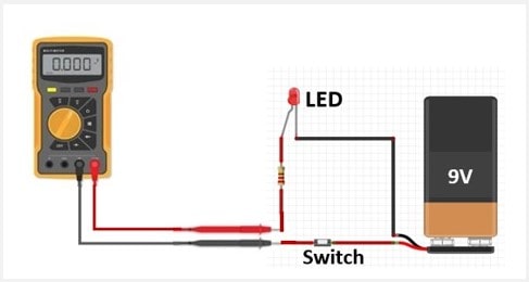
3.Turn the selection dial to the highest current range (10A or 20A) depending on which port your red probe was inserted.
4.Turn on the power and the current can be read from the multimeter display.
You can adjust the range to get more accurate readings especially if you are dealing with very low current.
When the red probe is in the socket for measuring current (mA or A), the meter is practically a short circuit and if you connect the meter to a voltage source when the lead is still in this position, you may end up destroying your multimeter. Therefore, always remember to return the red probe to the voltage socket (V) after measuring current.
Common mistakes when using a Multimeter.
- Not remembering to switch the test leads when switching between current sensing and voltage/resistance testing
- Exceeding the maximum input of the meter
- The selection dial being at a wrong function for the attempted measurement.
- Using a meter in an area above its stated rating.
- Using a multimeter when its battery is low. Replace the battery as soon as the battery indicator appears.
Safety precautions!
- Always check the probe leads before use and never use a multimeter where the leads are damaged.
- Never use a multimeter in circuits exceeding its rated voltage or current.
What multimeter should you buy?
As earlier stated, digital multimeters come in various models with different functionalities. For accurate measurements of DC and AC voltage, current, resistance, frequency, capacitance, continuity and diode test, I would recommend the Fluke 177, Victor VC890D and AstroAI models.
Clamp Meter
In case you are dealing with large currents above 20A, I would suggest you get a clamp meter. Clamp meters use either a current transformer or hall effect sensor to measure the magnetic field produced by flowing current. This enables you to measure very high currents by simply clamping over a single cable carrying the current. For this I recommend the Fluke 381 Clamp meter.

