How to use a Pulse Sensor with Arduino to measure Heart Rate.
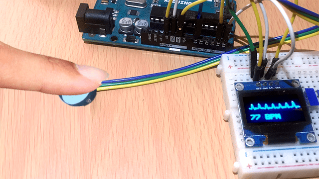
Pulse sensors are used in several projects for athletes, gaming, home appliances and mobile phone developers where there is need for reading heart rate data. In this tutorial I’ll focus on one of the low-power plug-and-play pulse sensor for Arduino.
Disclaimer: The pulse sensor am looking at is only for study purposes and should not be used as a medical device, if you have health concerns and need to check your heart rate, visit a medical doctor.
What is a pulse sensor?
A pulse sensor is a device used to detect a change in the volume of a blood vessel that occurs when the heart pumps blood. This volume change is called a pulse wave and is the basis of determining heart rate.
There are different ways of measuring heart rate for example using an electrocardiogram, photoelectric pulse wave, blood pressure measurement and phonocardiography.
In this tutorial am mainly looking at pulse sensors using the photoelectric pulse wave method. These are also called Optical heart rate sensors.
Pulse sensor Hardware Overview
This sensor has a heart shaped logo at the front side and this is where you place your finger when taking heart rate measurements. There is a green LED and just below the LED is APDS9008 photosensor as shown in the diagram below.
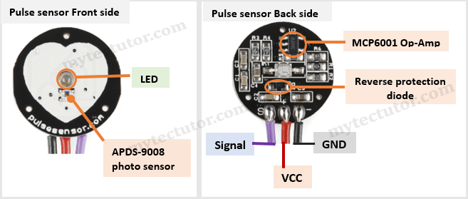
On the backside of the pulse senor module there are a number of electronic components like the MCP6001 Op-Amp and a bunch of resistors and capacitors that make up the R/C filter network and a reverse protection diode to prevent damage if the power leads are accidentally reversed.
The module operates from a 3.3 to 5V DC Voltage supply with a maximum current draw of 4mA.
In case you need to buy this pulse sensor and SSD1307 OLED you can visit the recommended link below:
Disclosure: These are affiliate links. I earn a commission as an Amazon Associate for qualifying purchases. I would appreciate your support in this way.
Pulse Sensor Pinout
This sensor has only three connection wires as shown in the pinout diagram above.
- GND – This is the ground terminal and is connected to the ground of a microcontroller.
- VCC – Power supply connected to +3.3V to +5V supply.
- S – This is the output signal.
The connection wires are not color coded therefore you need to check the backside of the pulse sensor module for the corresponding markings so that you are able to correctly identify the wires.
How does a Pulse Sensor Work?
Optical heart rate sensors can be classified as either transmission or reflection pulse sensors.
- Transmission-type pulse sensor measure pulse waves by emitting red or infrared light from the body surface and detecting the change in blood flow during heart beats as a change in the amount of light transmitted through the body. This method is limited to areas where light can easily penetrate, such as the fingertip or earlobe.
- Reflection-type pulse sensor like the one I am focusing on generates infrared, red color, or green color light toward the human body and measures the light which is reflected through a phototransistor or photodiode.
Generally, optical pulse sensors use the fact that oxygenated hemoglobin present in the blood of the arteries has the characteristic of absorbing incident light. Also, the volume of blood vessels changes with every heartbeat therefore a pulse sensor works by shining a green light (~ 550nm) on a blood vessel and measuring the amount of reflected light every time there is a change in blood vessel volume following heart contractions.
The photosensor measures changes in incident and reflected light over time and generates a pulse wave signal. This signal is then filtered and amplified using various electronic components on the pulse sensor to give a distinct heart-beat pulse reading.
This method of pulse detection using light is called Photoplethysmogram.
Connecting the Pulse Sensor to Arduino
To connect the Pulse Sensor to an Arduino you only need to connect three wires, that is, GND, VCC and Signal as shown in the schematic below.
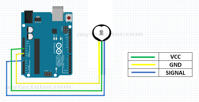
Don’t forget to check the backside of the sensor for the correct wiring. The positive voltage connects to ‘+’ and can be 3.3 or 5V. Ground connects to ‘-‘ and the ‘S’ wire is the analog signal output from the sensor and this will connect to the A0 analog input of an Arduino.
Calibration of pulse sensor.
Before using a pulse sensor to measure heart rate, you need to first determine which signals to consider as a heartbeat by setting a threshold value for the analog values read by the sensor. These threshold values differ depending on a number of factors like the supply voltage and model of the pulse sensor.
Code for calibration of the pulse sensor using Arduino.
The code below is used to calibrate the pulse sensor using Arduino Serial Plotter.
int LED13 = 13;
int Signal;
int Threshold = 518;

void setup() {
  pinMode(LED13,OUTPUT);
   Serial.begin(9600);
}

void loop() {
  Signal = analogRead(0);      .
  Serial.println(Signal);

   if(Signal > Threshold){
     digitalWrite(LED13,HIGH);
   } else {
     digitalWrite(LED13,LOW);
   }

  delay(10);
}
Code description.
First, the variables for on-board LED, Signal and Threshold signal are declared. Since these are analog signals, the value can range from 0-1024.
In the setup section, the on-board LED is set at OUTPUT and also initialize serial communication.
In the loop section, read the pulse sensor’s analog signal value and send the value to the serial plotter.
An if statement is used to compare the analog signal to the threshold value and if the signal value is above the threshold, the on-board LED will turn ON otherwise it will be OFF.
Upload the above code to Arduino board and open the Serial Plotter. Place a finger lightly on the front side of the pulse sensor and you will observe the pulse waveform using a Serial plotter and the corresponding blinking of the on-board LED.
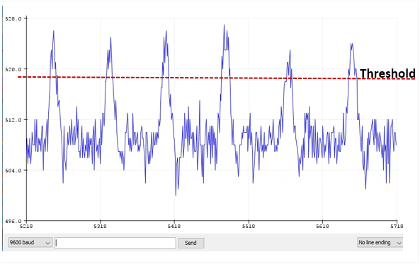
To calibrate the pulse sensor, you keep on varying the threshold signal from 0 to 1023 while observing the onboard LED blinking sequence and comparing to your own heartbeat got by touching and feeling the pulse in your wrist or neck. Normally the threshold is between 500 and 570 if you are supplying 5V to the pulse sensor. In my case I used 518.
For the best readings, you should press the sensor neither too tightly nor too lightly! Otherwise, you will not observe any signal.
Arduino PulseSensor Playground library.
The PulseSensor Playground library comes with various example sketches that you can use as reference for writing your own code for using the pulse sensor with Arduino.
To install the library, go to the Sketch > Include Library > Manage Libraries… to open the Library Manager and search for ‘pulsesensor’. Look for PulseSensor Playground and Install. You can get the example code sketches by going to the File > Examples > PulseSensor Playground.
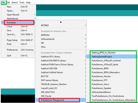
The GettingStartedProject example sketch is the same as the code I have given above for calibrating the pulse sensor.
Using Pulse sensor with Arduino to display Heart Rate on SSD1306 OLED.
After calibrating the pulse sensor, I’ll now show you a simple practical application of this sensor where you can display the pulse waveform and the corresponding heart rate in beats per minute (BMP) reading on an SSD1306 OLED.
Before proceeding you should know how to use the SSD1306 OLED with Arduino and in case you need assistance on this issue you can visit my other tutorial where I have written in-depth about the SSD1306 OLED and its use with Arduino:
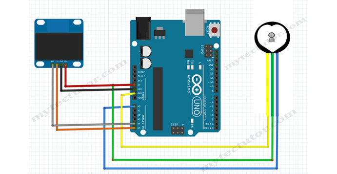
The setup is as shown in the schematic below. The SSD1306 OLED uses I2C communication and therefore we simply connect the SDA and SCL to A4 and A5 for Arduino UNO
Code for pulse sensor with Arduino and SSD1306 OLED.
#include <Adafruit_SSD1306.h>

#define OLED_Address 0x3C
Adafruit_SSD1306 oled(128, 64);

int x=0;
int lastx=0;
int lasty=0;
int LastTime=0;
int ThisTime;
bool BPMTiming=false;
bool BeatComplete=false;
int BPM=0;
#define UpperThreshold 518
#define LowerThreshold 509

void setup() {
  oled.begin(SSD1306_SWITCHCAPVCC, OLED_Address);
  oled.clearDisplay();
  oled.setTextSize(2);
}


void loop()
{
  if(x>127)
  {
    oled.clearDisplay();
    x=0;
    lastx=x;
  }

  ThisTime=millis();
  int value=analogRead(0);
  oled.setTextColor(WHITE);
  int y=60-(value/16);
  oled.writeLine(lastx,lasty,x,y,WHITE);
  lasty=y;
  lastx=x;
  // calc bpm

  if(value>UpperThreshold)
  {
    if(BeatComplete)
    {
      BPM=ThisTime-LastTime;
      BPM=int(60/(float(BPM)/1000));
      BPMTiming=false;
      BeatComplete=false;
      tone(8,1000,250);
    }
    if(BPMTiming==false)
    {
      LastTime=millis();
      BPMTiming=true;
    }
  }
  if((value<LowerThreshold)&(BPMTiming))
    BeatComplete=true;

    // display bpm
  oled.writeFillRect(0,50,128,16,BLACK);
  oled.setCursor(0,50);
  oled.print(BPM);
  oled.print(" BPM");
  oled.display();
  x++;
}
Limitations of this Pulse sensor.
As pointed out earlier, this pulse sensor is very sensitive to movement and infrared radiation therefore is only good to use indoors and when your hand is still. This is one of the reasons why you cannot use this sensor as a medical device.

