How to use TB6560 Stepper Motor Driver with Arduino.
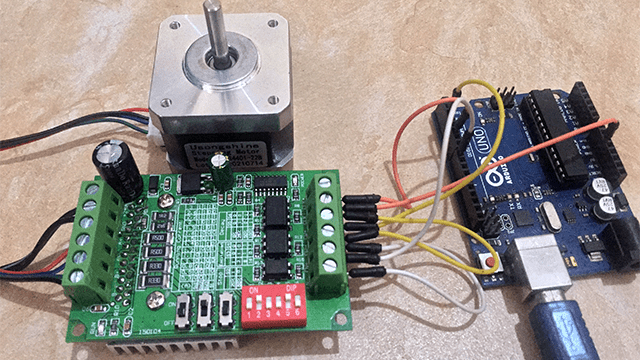
TB6560 Stepper motor driver is a low-cost motor driver suitable for controlling larger stepping motors like NEMA size 17 to 23 that are used in applications requiring low vibration, high speed and high precision for example 3D printers, laser cutters, engraving machines, robots and so on.
In this tutorial I’ll look at the hardware specifications of the TB6560 driver and how it can be interfaced with Arduino.
TB6560 stepper motor hardware and pinout description.
The TB6560 stepper motor driver is based on Toshiba TB6560AHQ stepping motor IC with a 6N137 high-speed Optocoupler providing low-vibration, high-performance forward and reverse driving of
a two-phase bipolar stepping motors using only a clock signal.
Specifications
- Working voltage of 10~35V DC. Recommended supply voltage of 24V DC.
- Rated maximum output current of ± 3A with 3.5A peak.
- Suitable for 2 or 4-phase, 4 or 6 wire stepper motors with a maximum load current of 3A.
- Low voltage shutdown, overheating and overcurrent protection circuit to ensure optimal performance.
- Adjustable load current protection and decay modes.
- Excitation modes: 1/2, 1/8, 1/16 step
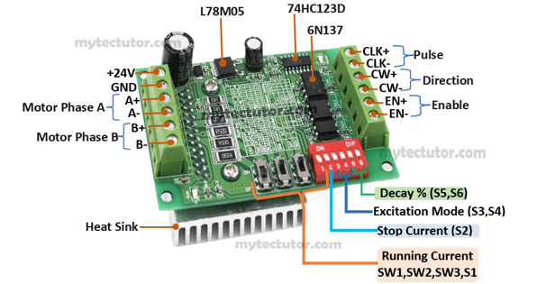
The TB6560 stepper motor driver has three SPST switches SW1, SW2, SW3 and DIP switches S1 to S6. These switches are used to adjust the output current, excitation mode and percentage decay. There are tables printed on top of the driver module showing how to set the switches to get the requires settings for these properties.
Do not adjust the switches when the motor driver is powered!
Running Current and Stop current settings
SPST switches SW1, SW2 and SW3, as well as the DIP switch S1 are used to set the output current. This should be close to your stepper motor’s required input current.
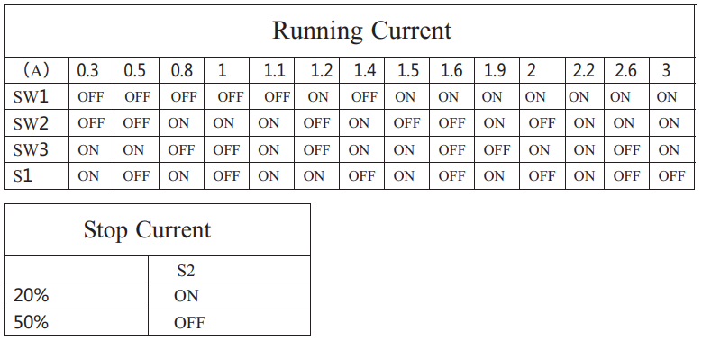
The DIP switch S2 defines the stop current and either sets it to 20% when ON or 50% when OFF. The stop current is the current used to hold the motor shaft at a stopped position and should be as low as possible to minimize unnecessary heating of the motor. You can increase this value if your motor can not hold its position.
Excitation Mode and Decay settings.
The DIP switches S3 and S4 are for setting the excitation mode and S5 and S6 are for setting decay percentage. The tables below show how these switches need to be set in order to achieve the desired excitation mode and decay.

The excitation mode gives microstep settings for TB6560 driver. Typically, stepper motors in full step mode make 200 steps per revolution which is a step size of 1.8°. However, microstepping drivers like TB6560 provide higher resolutions thereby can drive stepper motors in other step modes like ½ step mode which will give 400 microsteps per revolution.
TB6560 stepper motor driver goes up to 1/16 step mode which gives 3200 steps per revolution. Smaller microstep settings result in smoother and quieter operation but limit the top speed that you can achieve when controlling the stepper motor driver with a microcontroller like Arduino.
The decay setting controls how the driver chip handles the back EMF from the motor. You can adjust these settings and observe how they affect the performance of the motor.
TB6560 vs TB6600 Stepper motor driver.
When purchasing TB6560 driver, you will also come across the TB6600 stepper motor driver which can appear similar to TB6560 in the way they are connected to microcontrollers like Arduino and also uses the same code. However, these two drivers are quite different and I have done detailed comparison of these drivers in my other tutorial which you can refer to using the link below.
Connecting TB6560 Stepper motor driver to Arduino.
The connection is done as shown in the schematic below. I have used a common cathode configuration where all the negative control signals and enable are all connected to ground.
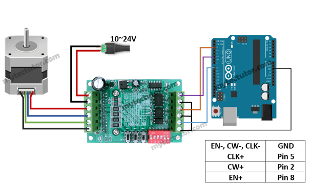
The pulse (CLK+), direction (CW+) and enable (EN+) are connected to Arduino pins 5, 2 and 8 respectively.
You can leave the enable pins (EN- and EN+) unconnected meaning that the enable pin is always LOW and the driver is always enabled. However, if you want to control the motor driver using software then you need to connect EN- to ground and EN+ to a digital pin of Arduino as I have done.
Do not connect stepper motors with a current rating of more than 3A to the driver.
How to determine the correct pair of wires belonging to the same coil of the stepper motor.
You need to be careful when connecting the wires from the motor to the driver. A pair of wires from one coil or phase of the motor is connected to A-/A+ and the other to B-/B+.
To determine which pair of wires belongs to the same coil, simply choose a random pair of wires from the motor and connect their bare ends together. Then try to spin the shaft of the stepper motor and if you feel a lot of resistance, you have found a pair of wires from the same coil. If you can still spin the shaft freely, try another pair of wires.
You can also measure the resistance between the two wires using a digital multimeter. If the multimeter shows any resistance between the wires, then that pair of wires is from the same coil.
Code for controlling TB6560 Stepper motor driver with Arduino.
A microcontroller like Arduino can be used to control the speed, number of revolutions and direction of rotation of the stepper motor. I’ll use the code below as an example of how to move the stepper motor from 0° to 360°, then back to 0°, and so on. In my case I have set the driver to 1/8 step mode and using a 12V power supply with 1A.
int dirPin = 2;
int stepPin = 5;
int enPin =8;

int stepsPerRevolution = 1600; //for 1/8 step mode

int angle = 0;
int step = 0;
int stepDelay = 500;
int checkAngle = 0;
int a = 0;

void setup() {
  pinMode(stepPin, OUTPUT);
  pinMode(dirPin, OUTPUT);
  pinMode(enPin,OUTPUT);
  digitalWrite(enPin,LOW);
}

void loop()
{
  if (checkAngle == 0)   {a = +1; }
  if (checkAngle == 360) {a = -1; }

  angle = angle + a ;
  a = angle;
  step = map(a, 0, 360, 0, stepsPerRevolution);

  //If the data is +ve, then rotate to the right
  if (a == 1)
  {
    digitalWrite(dirPin, LOW);

    for (int i = 0; i < step; i++)
    {
      digitalWrite(stepPin, HIGH);
      delayMicroseconds(stepDelay);
      digitalWrite(stepPin, LOW);
      delayMicroseconds(stepDelay);
    }

  }

  //If the data is -ve, then rotate to the left
  if (a == -1)
  {
    digitalWrite(dirPin, HIGH);

    for (int i = 0; i > step; i--)
    {
      digitalWrite(stepPin, HIGH);
      delayMicroseconds(stepDelay);
      digitalWrite(stepPin, LOW);
      delayMicroseconds(stepDelay);
    }
  }

  delay(100);
}
Code description
First the step (CLK+), direction (CW+) and enable (ENA+) pins are declared with their corresponding Arduino pins as 2, 5 and 8 respectively.
In the setup() section, all the motor control pins are declared as digital OUTPUT. I also enable the driver by setting the enable pin LOW.
The loop() section determines the number of steps the motor will take. The four lines of code below will send a pulse to the step pin resulting in one microstep.
 digitalWrite(stepPin, HIGH);
 delayMicroseconds(stepDelay);
 digitalWrite(stepPin, LOW);
 delayMicroseconds(stepDelay);
Controlling the number of steps or revolutions:
The for loop repeats the above lines of code a given number of times which represents the steps per revolution. For example, if the driver is set to 1/8 step mode, then the code in the for loop has to be executed 1600 times to get 1 revolution.
for(int i = 0; i < step; i++) {
    digitalWrite(stepPin,HIGH);
    delayMicroseconds(stepDelay);
    digitalWrite(stepPin,LOW);
    delayMicroseconds(stepDelay);
  }
I have used the map() function to divide the 360⁰ into the corresponding number of steps to be taken by the motor to complete one revolution.
Controlling motor rotation direction.
The direction of rotation of the stepper motor is determined by setting the direction (CW+) pin either HIGH or LOW and depending on how you connected the stepper motor, when the CW pin is set HIGH, the motor will turn clockwise and when set LOW it turns counter clockwise.
Controlling speed of rotation of the motor.
The speed of the stepper motor is determined by the frequency of the pulses we send to the STEP pin which is set using the delayMicroseconds() function. The shorter the delay, the higher the frequency and therefore the faster the motor runs.
Controlling TB6560 Driver using AccelStepper library
The AccelStepper library written by Mike McCauley contains a number of functions that simplify the control of stepper motors with Arduino using TB6650 driver and many other stepping motor drivers.
As mentioned earlier, TB6560 driver uses the same code as TB6600 driver and I have gone in detail on how to use the AccelStepper library with TB6600 driver in another tutorial which you can use as reference using the link below.
