TB6600 Stepper Motor Driver with Arduino.

The TB6600 stepper motor driver is used to control larger two-phase bipolar stepper motors like NEMA 23 motors used in 3D printers, CNC machines and robots. In this tutorial I’ll describe the TB6600 motor driver hardware in detail and also demonstrate how to control the driver with Arduino.
TB6600 Stepper Motor driver hardware description.
The TB6600 Stepper motor driver was originally built around TB6600HG stepping motor IC made by Toshiba. However nowadays many of these drivers have a TB67S109AFTG IC also made by Toshiba.
These chips are almost similar in performance and specifications but the TB6600HG is larger and has a higher peak current rating of up to 5A compared to the smaller TB67S109AFTG chip with a peak current rating of 4A. Also, the TB6600HG only supports up to 1/16 microstepping while the TB67S109AFTG goes up to 1/32.
The driver has over-current, under-voltage shutdown, and overheating protection. Other specifications can differ slightly depending on the manufacturer and therefore you should always check the datasheet of your driver before use.
Difference between TB6600 and TB6560 Stepper Motor drivers.
The TB6560 stepper motor driver can easily be confused with TB6600 model since these drivers can both be controlled using the same connections and code. However, they have some major differences that I’ll list in the comparison table below.

From the table above, TB6600 driver has a higher maximum operating voltage and current and can go up to 1/32 microstepping. Also, the TB6600 has a better heatsink. Therefore, if you want to control larger stepper motors with higher resolution, the TB6600 would be a better choice.
I have another tutorial dedicated to the TB6560 stepper motor driver which you can refer to using the link below.
Connecting TB6600 Stepper motor driver to Arduino.
The connection is rather simple and done as illustrated below. I will be connecting the driver in a common cathode configuration, that is, all the negative sides of the control signal will be connected to ground.
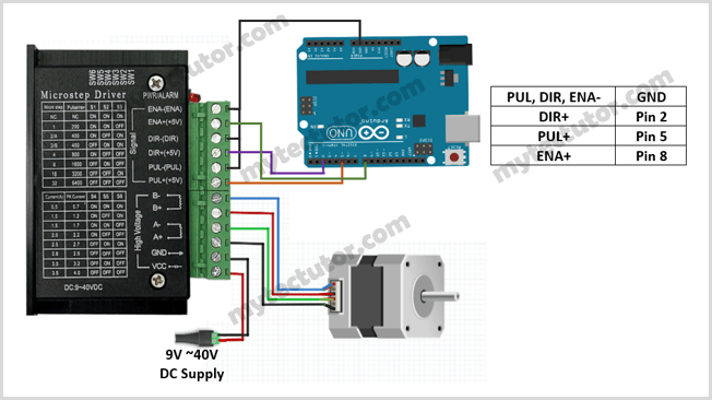
Make sure that you do not connect stepper motors with a current rating of more than 3.5 A to the driver.
A+,A- and B+,B- are the connections for the 4 wire bipolar stepper motor phases or coils. A pair of wires from one coil of the motor gets connected to A- and A+ and the other to B- and B+.
Determining which wires from the stepper motor belong to the same coil.
In case you are not sure which pair of wires belongs to the same coil, you can choose a random pair of wires from the motor and connect their bare ends together. Then try to spin the shaft of the stepper motor and if you feel a lot of resistance, you have found a pair of wires from the same coil. If you can still spin the shaft freely, try another pair of wires.
Alternatively, you can measure the resistance between the two wires using a digital multimeter. If the multimeter shows any resistance between the wires, then that pair of wires is from the same coil.
The enable pins (ENA- and ENA+) can be left unconnected meaning that the enable pin is always LOW and the driver is always enabled. However, in my case ENA- is connected to ground and ENA+ is connected to a digital pin of Arduino. This makes controlling the driver via software easier.
Adjusting Microsteps and Current
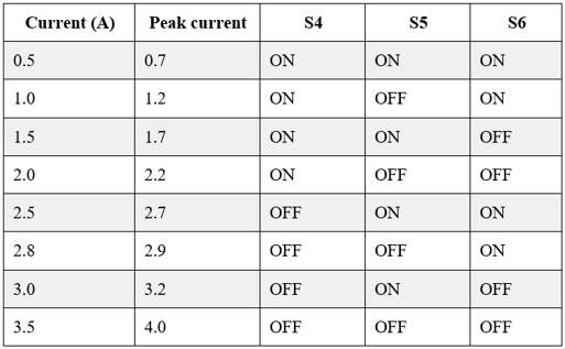
The TB6600 stepper motor driver has DIP switches used to set the microsteps and current depending on the specifications and application of the stepper motor being used. A table with microstep and current settings is printed on top of the driver case.
In full step mode, stepper motors normally make 200 steps per revolution which gives a step size of1.8°. The TB6600 driver supports microstepping mode which allows higher resolutions for stepper motors by allowing intermediate step locations through energizing the motor phases with intermediate current levels.
For example, when in ½ step mode, the stepper motor will make 400 microsteps per revolution and in ¼ step mode it will make 800 microsteps per revolution.
The TB6600 microstep settings can be changed by turning DIP switches S1, S2 and S3 on or off in specific order as shown in the table below. The settings below are for a 1/32 microstepping driver.
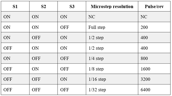
A smaller microstep setting will result in a smoother and quieter operation but will limit the top speed that you can achieve when controlling the stepper motor driver with a microcontroller.
Do not adjust the dip switches when the driver is powered.
Switches S4, S5 and S6 are used to adjust the current that goes to the motor when it is running. It is better to start with a current level of 1 A and incase the motor is missing steps or stalling; you can go on increasing the current level.
Code for controlling TB6600 Stepper motor driver with Arduino.
A microcontroller like Arduino can be used to control the speed, number of revolutions and direction of rotation of the stepper motor. The code below is an example of how this can be achieved.
const int stepPin = 5;
const int dirPin = 2;
const int enPin = 8;

void setup() {
  pinMode(stepPin,OUTPUT);
  pinMode(dirPin,OUTPUT);
  pinMode(enPin,OUTPUT);
  digitalWrite(enPin,LOW);

}

void loop() {
  digitalWrite(dirPin,HIGH); // Enables the motor to move in a particular direction
  for(int x = 0; x < 800; x++) {
    digitalWrite(stepPin,HIGH);
    delayMicroseconds(500);
    digitalWrite(stepPin,LOW);
    delayMicroseconds(500);
  }
  delay(1000); // One second delay
  digitalWrite(dirPin,LOW); //Changes the direction of rotation
  for(int x = 0; x < 800; x++) {
    digitalWrite(stepPin,HIGH);
    delayMicroseconds(500);
    digitalWrite(stepPin,LOW);
    delayMicroseconds(500);
  }
  delay(1000);
}
Code description
First the step (PUL+), direction (DIR+) and enable (ENA+) pins are declared with their corresponding Arduino pins as 5, 2 and 8 respectively.
In the setup() section, all the motor control pins are declared as digital OUTPUT. I also enable the driver by setting the enable pin LOW.
The loop() section determines the number of steps the motor will take. The four lines of code below will send a pulse to the step pin resulting in one microstep.
digitalWrite(stepPin, HIGH);

delayMicroseconds(500);

digitalWrite(stepPin, LOW);

delayMicroseconds(500);
Controlling the number of steps or revolutions:
The for loop repeats the above lines of code a given number of times which represents the steps per revolution. For example, if the driver is set to ¼ step mode, then the code in the for loop has to be executed 800 times to get 1 revolution, that is,
for(int i = 0; i < 800; i++) {
    digitalWrite(stepPin,HIGH);
    delayMicroseconds(500);
    digitalWrite(stepPin,LOW);
    delayMicroseconds(500);
  }
If the motor is set to 1/8 step mode, then the above for loop would result in half a revolution.
Controlling motor rotation direction.
The direction of rotation of the stepper motor is determined by setting the direction (DIR+) pin either HIGH or LOW and depending on how you connected the stepper motor, when the DIR pin is set HIGH, the motor will turn clockwise and when set LOW it turns counter clockwise.
Controlling speed of rotation of the motor.
The speed of the stepper motor is determined by the frequency of the pulses we send to the STEP pin which is set using the delayMicroseconds() function. The shorter the delay, the higher the frequency and therefore the faster the motor runs.
Controlling TB6600 Driver using AccelStepper library
Mike McCauley has written the AccelStepper library that contains a number of functions that simplify the control of stepper motors with Arduino using TB6600 driver and many other stepper motor drivers.
This library can be installed directly from the Arduino IDE by going to Tools > Manage Libraries… to open the Library Manager where you can search for ‘AccelStepper’ and look for and install the latest version of the library by Mike McCauley.
Example code for controlling TB6600 Stepper motor driver with Arduino using AccelStepper library.
The code below is for moving the motor back and forth with a speed of 1000 steps/s and an acceleration of 500 steps/s2. The driver is in ¼ step mode but you can change the mode and the speed and acceleration settings and observe what happens.
#include <AccelStepper.h>
#define dirPin 2
#define stepPin 3
#define motorInterfaceType 1

// Create a new instance of the AccelStepper class:
AccelStepper stepper = AccelStepper(motorInterfaceType, stepPin, dirPin);

void setup() {
stepper.setMaxSpeed(1000);
stepper.setAcceleration(500);
}

void loop() {
stepper.moveTo(8000);
stepper.runToPosition();
delay(1000);
// Move back to zero:
stepper.moveTo(0);
stepper.runToPosition();
delay(1000);
}
Code description:
First, you have to include the AccelStepper library and then declare the TB6600 and Arduino connections and the motor interface type. When using a step and direction driver, the motor interface type must be set to 1.
Then you need to create a new instance of the AccelStepper class with the appropriate motor interface type and connections. You can even create multiple instances of the AccelStepper class with different names and pins which allows you to easily control two or more stepper motors at the same time.
In the setup() section, we use the setMaxSpeed() and setAcceleration() functions to set the maximum speed and acceleration or deceleration. In the loop section, the moveTo() function is used to set the target position in steps of the motor and the runToPostion() function moves the motor to the target position with the set acceleration or deceleration.
