TCS3200 Color Sensor interfacing with Arduino.
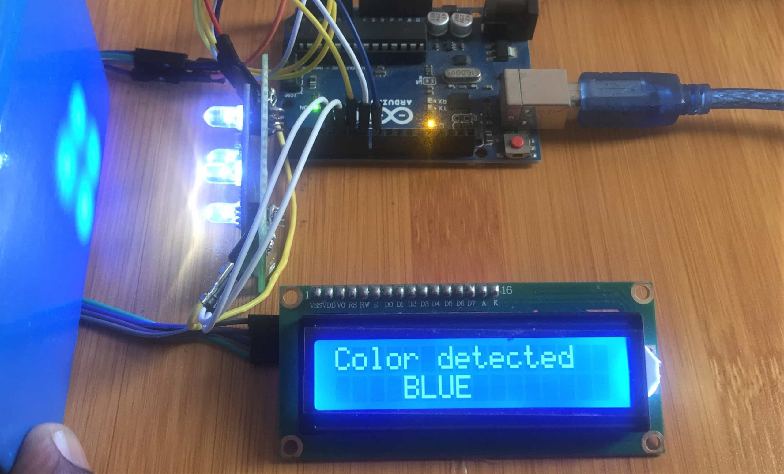
Ability to detect colors is among the most on demand qualities in a number of electronic systems and for beginners this is where the TCS3200 color sensor comes in handy. In this tutorial we show how this sensor can be interfaced with Arduino for application various projects like color sorting machines and robots.
TCS3200 Color Sensor description
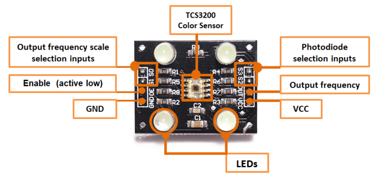
This is a color light-to-frequency converter that combine configurable silicon photodiodes and a current-to-frequency converter on a single monolithic CMOS integrated circuit. The output is a square wave (50% duty cycle) with frequency directly proportional to light intensity.
The full-scale output frequency can be scaled by one of three preset values via two control input pins. Digital inputs and digital output allow direct interface to a microcontroller in this case the Arduino.
In the TCS3200, the light-to-frequency converter reads an 8 x 8 array of photodiodes. 16 photodiodes have blue filters, 16 photodiodes have green filters, 16 photodiodes have red filters, and 16 photodiodes are clear with no filters.
All photodiodes of the same color are connected in parallel. Pins S2 and S3 are used to select which group of photodiodes (red, green, blue, clear) are active.
The pins S0 and S1 are Output frequency scaling selection inputs, pin number 3 is Output Enable pin and also it is a active low pin normally connected with ground supply it Enable for fo.

Connecting the TCS3200 Color sensor to Arduino.
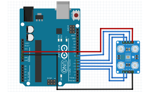
Before we can use this color sensor in an application, we need to first do some calibration so that we can know the frequency ranges of the various colors detected by the sensor. This is done by connecting the TCS3200 color sensor to the Arduino as shown below with:
S0 to Arduino Pin 4
S1 to Arduino Pin 5
S2 to Arduino Pin 6
S3 to Arduino Pin 7
OUT to Arduino Pin 8
Code for calibration of the TCS3200 Color Sensor.
// TCS230 or TCS3200 pins wiring to Arduino
#define S0 4
#define S1 5
#define S2 6
#define S3 7
#define sensorOut 8

// Stores frequency read by the photodiodes
int redFrequency = 0;
int greenFrequency = 0;
int blueFrequency = 0;

void setup() {
  // Setting the outputs
  pinMode(S0, OUTPUT);
  pinMode(S1, OUTPUT);
  pinMode(S2, OUTPUT);
  pinMode(S3, OUTPUT);

  // Setting the sensorOut as an input
  pinMode(sensorOut, INPUT);

  // Setting frequency scaling to 20%
  digitalWrite(S0,HIGH);
  digitalWrite(S1,LOW);

   // Begins serial communication
  Serial.begin(9600);
}
void loop() {
  // Setting RED (R) filtered photodiodes to be read
  digitalWrite(S2,LOW);
  digitalWrite(S3,LOW);

  // Reading the output frequency
  redFrequency = pulseIn(sensorOut, LOW);

   // Printing the RED (R) value
  Serial.print("R = ");
  Serial.print(redFrequency);
  delay(100);

  // Setting GREEN (G) filtered photodiodes to be read
  digitalWrite(S2,HIGH);
  digitalWrite(S3,HIGH);

  // Reading the output frequency
  greenFrequency = pulseIn(sensorOut, LOW);

  // Printing the GREEN (G) value
  Serial.print(" G = ");
  Serial.print(greenFrequency);
  delay(100);

  // Setting BLUE (B) filtered photodiodes to be read
  digitalWrite(S2,LOW);
  digitalWrite(S3,HIGH);

  // Reading the output frequency
  blueFrequency = pulseIn(sensorOut, LOW);

  // Printing the BLUE (B) value
  Serial.print(" B = ");
  Serial.println(blueFrequency);
  delay(100);
}
When this code is uploaded, an object with the color whose frequency is needed is brought close to the sensor and we observe the changes in frequencies on the serial monitor as illustrated below.
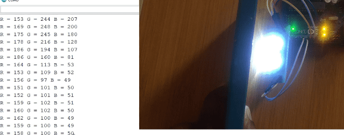
From the illustration above you can observe that the frequency values for the blue color are low compared to red and green colors. This is because the object placed in front of the sensor is blue. The upper and bottom frequency limits for the blue color are then saved because they will be needed later.
This procedure is repeated for the red and green colors and in each case you should save the frequency limits.
The major challenge to detection of color using this sensor is the interference of light from the surrounding. To avoid this you should either surround the LEDs on the sensor with a black screen to shield out external light or you have to reduce the lighting in the room.
A simple application of the TCS3200 Color sensor.
After calibration of the sensor we can be able to use it in a number of applications. In the example below we can be able to detect the color of the object placed in front of the sensor and display the color on an LCD.
We only add an I2C LCD to the setup of the color sensor and Arduino. You can first do a review of how to use the I2C LCD from my other post:
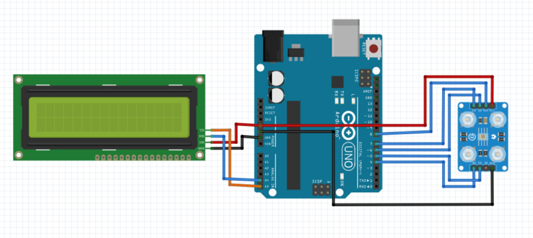
Code
#include <Wire.h>
#include <LiquidCrystal_I2C.h>
//I2C pins declaration
LiquidCrystal_I2C lcd(0x27, 2, 1, 0, 4, 5, 6, 7, 3, POSITIVE);
// TCS230 or TCS3200 pins wiring to Arduino
#define S0 4
#define S1 5
#define S2 6
#define S3 7
#define sensorOut 8

// Stores frequency read by the photodiodes
int red = 0;
int green = 0;
int blue = 0;

void setup() {
  lcd.begin(16,2);
  lcd.backlight();
  // Setting the outputs
  pinMode(S0, OUTPUT);
  pinMode(S1, OUTPUT);
  pinMode(S2, OUTPUT);
  pinMode(S3, OUTPUT);

  // Setting the sensorOut as an input
  pinMode(sensorOut, INPUT);

  // Setting frequency
scaling to 20%
  digitalWrite(S0,HIGH);
  digitalWrite(S1,LOW);
}

void loop(){
   lcd.setCursor(0,0);
   lcd.print("Color detected");
   color();

   if(red<blue && red<green && red<40){
      lcd.setCursor(0,1);
      lcd.print("    RED     ");
      delay(1000);
   }
   else if(blue < red && blue < green) {
      lcd.setCursor(0,1);
      lcd.print("    BLUE    ");
      delay(1000);
   }
   else if (green < red && green < blue) {
      lcd.setCursor(0,1);
      lcd.print("    GREEN   ");
      delay(1000);
   }
   else {
 lcd.setCursor(0,0);
      lcd.print("   NO COLOR   ");
      lcd.setCursor(0,1);
      lcd.print("   DETECTED   ");
     delay(5000);
  }

}

void color() {
  // Setting RED (R) filtered photodiodes to be read
  digitalWrite(S2,LOW);
  digitalWrite(S3,LOW);
  // Reading the output frequency
  red = pulseIn(sensorOut, LOW);
  delay(100);

  // Setting GREEN (G) filtered photodiodes to be read
  digitalWrite(S2,HIGH);
  digitalWrite(S3,HIGH);
  // Reading the output frequency
  green = pulseIn(sensorOut, LOW);
  delay(100);

  // Setting BLUE (B) filtered photodiodes
to be read
  digitalWrite(S2,LOW);
  digitalWrite(S3,HIGH);
  // Reading the output frequency
  blue = pulseIn(sensorOut, LOW);
  delay(100);
}
When this code is uploaded to the Arduino, the sensor will be able to detect if the object in front of it is red, green or blue and the color will be displayed on the LCD.
You can try to improve this setup by giving the sensor the capability of detecting other colors apart from red, green and blue.

