A seven segment display is used in projects where we want to display simple digits or letters like in digital counters and clocks. It is a relatively cheaper option compared to other display devices like LCDs. In this tutorial I will show how to interface a 7 segment display with Arduino.
7 segment Display Hardware overview.
A 7-segment display is simply an arrangement of seven LEDs where each segment represents an LED. These are turned on in a given pattern to be able to show a given digit or letter. The seven segments are labeled a to g. Another segment is usually added to represent a decimal point which is important in some applications.
The diagram below shows the arrangement of the segments and the corresponding pins. The pins a, b, c, d, e and f control the lighting of the individual segments. The DP pin is for controlling the decimal point. The COM pin is connected to either GND or VCC of the microcontroller depending on the type of display.

Internally, one pin of each of the segment LED is connected to the outer pin that can be seen. The other LED pins are connected together to form a common pin. To be able to turn on a specific part of the display, you simply turn the pin connected to that segment HIGH or LOW. This makes some segments light and others dark thereby giving the desired character pattern for the digit or letter to be displayed.
Common Cathode or Common Anode?
Since the seven segment display is a collection of LEDs, and each LED has a cathode(negative) and anode(postive) terminal, the way these LEDs are connected internally determines the type of display which then affects how the code for running the display is written.
In a common cathode seven-segment display, the cathodes of all seven LEDs and the dot LED are connected giving a COM(common) pin. When using this display, the COM pin is connected to the GROUND of the microntroller and the segment pins will be turned on by supplying a +5v signal to the corresponding digital pin where the anode is connected.
The common anode display is the exact opposite therefore the anode of all the LEDs are connected together to form the COM pin. In this case the COM pin is connected to 5V and the individual segments will be turned on by grounding their cathode pins. The diagram below shows the internal structure of the common cathode and common anode seven-segment displays.

Testing the type of display with a multimeter.
It is always good to know the type of display you are using before including it in your setup and writing code. This can easily be done by connecting one of the probes of your multimeter in continuity mode to one of the COM pins and the other probe touches any of the segment pins.
If the display is a common cathode type then when the negative probe of the multimeter is connected to the COM pin and the positive probe is connected to any other pins, then the corresponding segment will light.
If you interchange the probes then nothing happens.For the common anode type you connect the positive probe to the COM pin and the negative probe to any other pin for the corresponding segment to light.
How does the 7 segment display work?
This display works by lighting individual segment LEDs in order to show a specific digit or letter. For example when all the LEDs are on then the digit “8” is displayed and when segments a,b,d,e and g are turned on the digit “2” is displayed. Using this logic, digits from 0 to 9 and characters from A through F can be displayed.
The truth table below is an example of how the 7 segment display works. It shows how the individual LEDs from a to g are either on or off depending on the digit to be displayed. This table is for a common cathode display whereby 1 represents ON and 0 represents OFF. The truth table for common anode 7-segment display is the exact opposite of the common cathode 7-segment display.

I have also included a column for the hexadecimal values which can be very useful when writing code. You can complete the table by finding the binary and hexadecimal values for other digits and characters keeping in mind the type of display you are using.
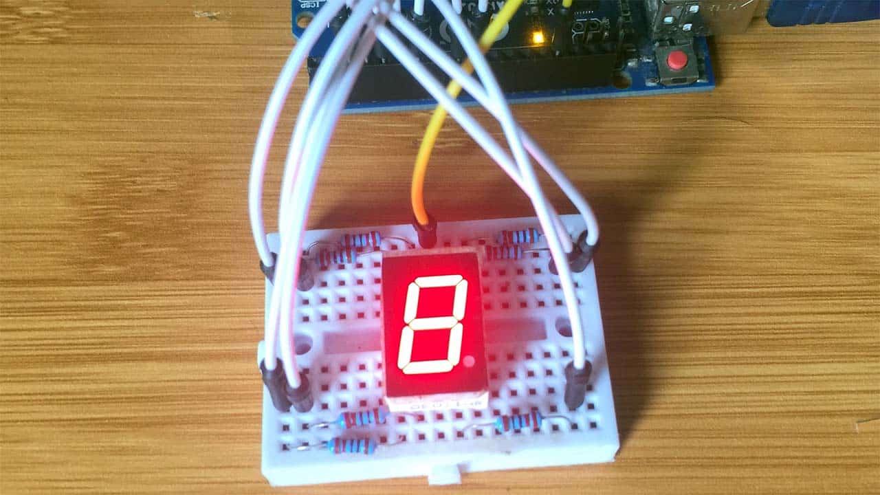
Connecting the Display to Arduino UNO.
Before connecting the display to Arduino you need to first know the type of display being used. In my case, it is a common cathode display therefore one of the common pins is going to be connected to the GND pin of the Arduino. If you are using a common anode display then the common pin is connected to 5V pin of the Arduino.
The remaining pins for the individual segments of the display are connected to the digital pins of the Arduino. The connections can be done as shown in the diagram below.

NOTE: The display can work without using the current limiting resistors but it is always good practice to include them to avoid damaging the display. The LED in each segment can draw up to 15mA so the current limiting resistor should be about 220Ω.
Code for running the 7 segment display.
The code for running this display is not very complex since it is mainly about changing the sequence of lighting of individual LEDs. The example below is using a custom function displayDigit() which includes conditional statements for determining which segment LEDs are on for displaying specific digits.
int a = 2;  //For displaying segment "a"
int b = 3;  //For displaying segment "b"
int c = 4;  //For displaying segment "c"
int d = 5;  //For displaying segment "d"
int e = 6;  //For displaying segment "e"
int f = 8;  //For displaying segment "f"
int g = 9;  //For displaying segment "g"
void setup() {
  pinMode(a, OUTPUT);  //A  pinMode(b, OUTPUT);  //B
  pinMode(c, OUTPUT);  //C
  pinMode(d, OUTPUT);  //D
  pinMode(e, OUTPUT);  //E
  pinMode(f, OUTPUT);  //F
  pinMode(g, OUTPUT);  //G
}
void displayDigit(int digit)
{
 //Conditions for displaying segment a
 if(digit!=1 && digit != 4)
 digitalWrite(a,HIGH);

 //Conditions for displaying segment b
 if(digit != 5 && digit != 6)
 digitalWrite(b,HIGH);

 //Conditions for displaying segment c
 if(digit !=2)
 digitalWrite(c,HIGH);

 //Conditions for displaying segment d
 if(digit != 1 && digit !=4 && digit !=7)
 digitalWrite(d,HIGH);

 //Conditions for displaying segment e
 if(digit == 2 || digit ==6 || digit == 8 || digit==0)
 digitalWrite(e,HIGH);

 //Conditions for displaying segment f
 if(digit != 1 && digit !=2 && digit!=3 && digit !=7)
 digitalWrite(f,HIGH);
 if (digit!=0 && digit!=1 && digit !=7)
 digitalWrite(g,HIGH);

}
void turnOff()
{
  digitalWrite(a,LOW);
  digitalWrite(b,LOW);
  digitalWrite(c,LOW);
  digitalWrite(d,LOW);
  digitalWrite(e,LOW);
  digitalWrite(f,LOW);
  digitalWrite(g,LOW);
}
void loop(){
  for(int i=0;i<10;i++)
 {
   displayDigit(i);
   delay(1000);
   turnOff();
 }
}
When this code is uploaded to the Arduino, the digits from 0 to 9 are going to be displayed one at a time every after one second.
Using libraries.
Writing code for controlling the individual segment LEDs can be hectic and so some libraries have been developed to ease the use of 7 segment displays.
A common library I can recommend is the SevSeg.h library which has a number of functions for controlling these displays. The code below is an example using the SevSeg.h library to display digits one by one with a two seconds delay.
#include "SevSeg.h"
SevSeg sevseg;
void setup()
{
  //Set to 1 for single digit display
  byte numDigits = 1;
  //defines common pins while using multi-digit display. Left empty as we have a single digit display
  byte digitPins[] = {};
  //Defines arduino pin connections in order: A, B, C, D, E, F, G, DP
  byte segmentPins[] = {3, 2, 8, 7, 6, 4, 5, 9};
  bool resistorsOnSegments = true;
  //Initialize sevseg object. Uncomment second line if you use common cathode 7 segment
  sevseg.begin(COMMON_ANODE, numDigits, digitPins, segmentPins, resistorsOnSegments);
  //sevseg.begin(COMMON_CATHODE, numDigits, digitPins, segmentPins, resistorsOnSegments);
  sevseg.setBrightness(90);
}
void loop()
{
   //Display numbers one by one with 2 seconds delay
   for(int i = 0; i < 10; i++)
   {
     sevseg.setNumber(i);
     sevseg.refreshDisplay();
     delay(2000);
   }
}
Interfacing the 7 segment display with a 74HC595 shift register.
The main downside of connecting a 7 segment display directly to a microcontroller like the way I have demonstrated in the examples above is the use of many I/O pins. If we want to use more than one display or if the setup involves other components to connect to the microcontroller then this kind of connection is not practical. To solve the problem of the number of used I/O pins we can use a 74HC575 shift register.
This acts as a serial-to-parallel converter, that is, we serially send 8 bits of data, which represents the way we want to turn on the display using one signal pin into the shift register and the register can output the corresponding data pattern to its 8 output pins at once (parallel).When using this register, the number of pins we use to connect the 7 segment display to the Arduino board is significantly reduced from 8 to 3.

The connections above for the display and the shift register may be a bit complicated if you are not well familiar with the 74HC595 shift register so I will simplify them using a table shown below.

Code for using the display with 74HC595 shift register.
// Globals
const int dataPin = 4; // to 74HC595 pin 14
const int latchPin = 7; // to 74HC595 pin 12
const int clockPin = 8; //  to 74HC595 pin 11
// uncomment one of the following lines that describes your display
// and comment out the line that does not describe your display
// const char common = 'a'; // common anode
const char common = 'c'; // common cathode
unsigned int cnt = 0;
byte symbol, symbols[] = {
B11111100, // 0
B01100000, // 1
B11011010, // 2
B11110010, // 3
B01100110, // 4
B10110110, // 5
B10111110, // 6
B11100000, // 7
B11111110, // 8
B11110110, // 9
B11101110, // A
B00111110, // B
B10011100, // C
B01111010, // D
B10011110, // E
B10001110 // F
};
void setup() {
// initialize I/O pins
pinMode(dataPin, OUTPUT);
pinMode(latchPin, OUTPUT);
pinMode(clockPin, OUTPUT);
if( common == 'a' )
for(int i=0; i<sizeof(symbols); i++)
symbols[i] ^= B11111111;
}
void loop() {
symbol = symbols[cnt++%sizeof(symbols)] | (cnt%2);
digitalWrite(latchPin, LOW); // prepare shift register for data
shiftOut(dataPin, clockPin, LSBFIRST, symbol); // send data
digitalWrite(latchPin, HIGH); // update display
delay(500); // pause for 1/2 second
}
When the display is a common cathode type, if a bit value is 1, the corresponding segment is turned ON and when the bit is 0 the segment is turned OFF. This logic is reversed in a common anode display, therefore, all the 8 bit values in the byte are flipped if the global variable, “common” is equal to “a”, which converts 1s to 0s and 0s to 1s using the bitwise XOR (^) operator with B11111111 bit mask.
Before sending the bits into the 74HC595’s registers, the latchPin is set LOW. Then the shiftOut() function is called to transfer the bits and finally the latchPin is set HIGH to be able to display the corresponding character.


