A4988 Stepper Motor Driver with Arduino.
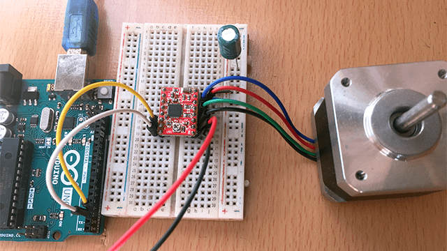
The A4988 stepper motor driver is used for controlling small and medium-sized bipolar stepper motors like NEMA 17 stepper motor used in 3D printers and CNC machines
I also have tutorials on other stepper motor drivers that you can check out using the links below;
A4988 Stepper motor driver hardware overview
This motor driver is based on the A4988 DMOS Microstepping Driver IC from Allegro with Translator and Overcurrent Protection.
Specifications
- Operating voltage of 8 – 35V
- Continuous current per phase of 1A and Maximum current per phase of 2A
- Logic voltage of 3 – 5.5V
- Microstep resolution of full, 1/2, 1/4, 1/8 and 1/16
- No reverse voltage protection
A4988 Stepper Motor driver Pinout
The A4988 stepper motor driver board has a total of 16 pins as shown below:
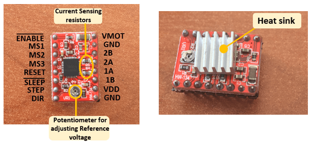
- GND and VMOT on the top right side are the connections for the motor power supply taking on 8V – 35V depending on the motor you are using.
- GND and VDD on the lower right side are power supply for the internal circuit of the A4988 driver. GND is connected to ground pin of the microcontroller and VDD is connected to 5V.
- 1A, 1B, 2A, 2B are output pins connected to the bipolar stepper motor coils. One coil of the stepper motor goes through 1A and 1B, and the other through 2A and 2B.
- DIR – used to determine the direction of rotation of a stepper motor. The motor spins clockwise or counter-clockwise depending on whether this pin is pulled LOW or HIGH.
- STEP – for controlling the microsteps of the motor by sending HIGH pulses to this pin. The faster the pulse, the faster the motor will spin.
- SLEEP – is an active low input. Pulling this pin LOW puts the driver into sleep mode, minimizing power consumption especially when the motor is not in use to save power.
- RESET – is also an active low input and when activated, it ignores all inputs sent to the “STEP” pin until deactivated. This pin is floating and if you are not using this pin, you can connect it to the SLEEP pin to make it high and enable the driver.
- ENABLE – This pin active low and is enabled by default so the driver is always enabled unless you pull it high.
- MS1, MS2, MS3 – Microstep selection pins used to set the microstep resolution depending on the different combinations of inputs as detailed in the next section.
The A4988 driver comes with a heatsink and it is good practice to install it before using the driver. This is because the A4988 driver IC has a maximum current rating of 2A per coil but if more than 1A per coil is supplied, a lot of heat is dissipated which can eventually damage the IC. Therefore to get more than 1A per coil, a heat sink is required.
A4988 Microstepping Settings
Stepper motors normally make 200 steps per revolution in full-step mode which gives a step size of1.8°. Motor drivers that supports microstepping mode like A4988 allow higher resolutions for stepper motors by allowing intermediate step locations through energizing the motor phases with intermediate current levels.
For example, when in ½ step mode, the stepper motor will make 400 microsteps per revolution and in ¼ step mode it will make 800 microsteps per revolution.
Microstep settings in A4988 can be changed by setting the appropriate logic levels for MS1, MS2 and MS3 pins to give one of five step resolutions as indicated below.
| MS1 | MS2 | MS3 | Microstep Resolution | Steps per revolution |
| Low | Low | Low | Full Step | 200 |
| High | Low | Low | 1/2 Step | 400 |
| Low | High | Low | 1/4 Step | 800 |
| High | High | Low | 1/8 Step | 1600 |
| High | High | High | 1/16 Step | 3200 |
Connecting A4988 Stepper Motor Driver to Arduino.
The A4988 stepper motor driver can be connected to a microcontroller like Arduino to control the speed, number of revolutions and direction of rotation of a stepper motor. However an important aspect to consider before using this driver is setting the current limit.
How To Set The Current Limit of A4988 Stepper Motor Driver.
It is crucial to set the current limit to prevent the current flowing through the stepper motor coils from exceeding the motor’s rated current. Excess current will overheat and eventually damage the motor and driver.
Also the best speed and torque for a given motor are achieved when the motor is running at its rated current.
The current limit can be got by measuring the voltage reference which corresponds to the maximum current that will flow to your stepper motor.
Reference Voltage is calculated from the formula
VREF = Imax . 8. Rs
Where
- Imax is the maximum motor current which can be found on the motor’s datasheet.
- Rs is the current sense resistor for the given motor. This can vary depending on the manufacturer. Values are usually 0.05Ω, 0.1Ω or 0.2Ω.
After calculating the Reference Voltage, you can now make adjustments to the motor driver by measuring the reference voltage between the driver’s potentiometer screw and ground. The connection is done as shown below where the SLEEP and RESET pins are bridged and power supplied to the driver through the ground and VDD pins. The power can be supplied from the 5V supply on Arduino.
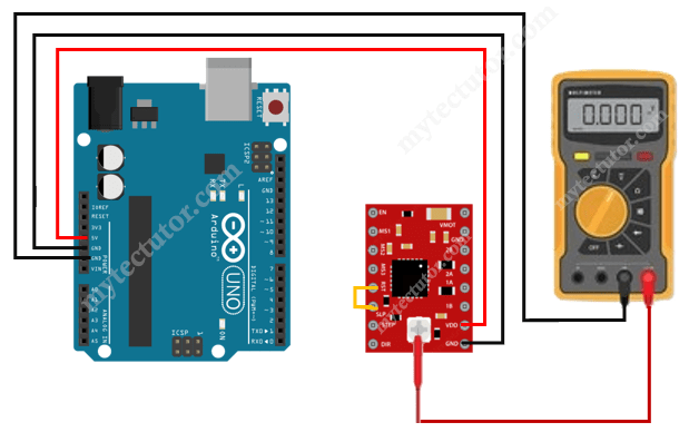
Next you need to adjust the reference voltage. You can use a small screw driver to connect the motor driver’s potentiometer to the positive lead of a multimeter using an alligator lead.
Set your multimeter to the DC voltage measurement and then place the head of the screwdriver onto the potentiometer. Adjust the voltage by turning the screwdriver anticlockwise or clockwise until the measured reference voltage equals the calculated value of VREF.
You don’t need to connect the stepper motor to the driver when setting the current limit
Driving A Stepper Motor Using A4988 Stepper Motor Driver And Arduino.
The schematic diagram below shows how the connection for Arduino UNO, A4988 Stepper motor driver and the stepper motor is done.
- The STEP and DIR pins are connected to Arduino digital pins 3 and 2 respectively.
- RESET and SLEEP are connected together
- 1A, 1B, 2A and 2B are connected to the stepper motor coils.
- VMOT is connected to 8-35V power supply and VDD shares the 5V from Arduino
- One of the GND goes to the Arduino ground and the other to the motor power supply ground.
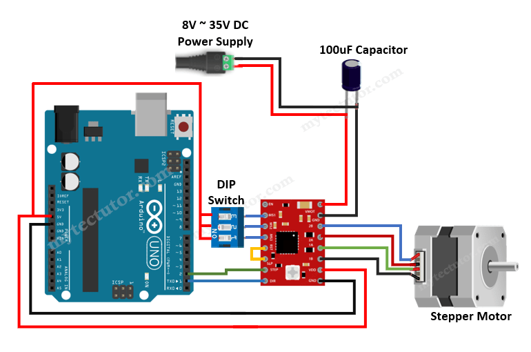
An electrolytic capacitor of 47μF – 100μF is connected between VMOT and GND to protect the motor driver from destructive LC voltage spikes especially when using long power leads.
I have also included a 3 way DIP switch connected to the microstep selection pins MS1, MS2 and MS3. This will enable you to adjust the microsteps for the motor by setting these pins either LOW or HIGH as described earlier.
If MS1, MS2 and MS3 are not connected, the driver operates in full-step mode.
How to determine which wires from the stepper motor belong to the same coil.
When connecting a 4 wire bipolar stepper motor to A4988 motor driver, 1A and 1B are connected to the two wires from a single motor coil while 2A and 2B are connected to another coil.
You need to know which pair of wires belongs to the same motor coil. This is done by choosing a random pair of wires from the motor and connecting their bare ends together. Then try spinning the shaft of the stepper motor. If you feel a lot of resistance, you have found a pair of wires from the same coil. If you can still spin the shaft freely, try another pair of wires.
Alternatively, you can measure the resistance between the two wires using a digital multimeter. If the multimeter shows any resistance between the wires, then that pair of wires is from the same coil.
Code for controlling Stepper motor using A4988 stepper motor driver and Arduino.
// Define pin connections & motor's steps per revolution
const int dirPin = 2;
const int stepPin = 3;
const int stepsPerRevolution = 200;

void setup()
{
	// Declare pins as Outputs
	pinMode(stepPin, OUTPUT);
	pinMode(dirPin, OUTPUT);
}
void loop()
{
	// Set motor direction clockwise
	digitalWrite(dirPin, HIGH);

	// Spin motor slowly
	for(int x = 0; x < stepsPerRevolution; x++)
	{
		digitalWrite(stepPin, HIGH);
		delayMicroseconds(2000);
		digitalWrite(stepPin, LOW);
		delayMicroseconds(2000);
	}
	delay(1000); // Wait a second

	// Set motor direction counterclockwise
	digitalWrite(dirPin, LOW);

	// Spin motor quickly
	for(int x = 0; x < stepsPerRevolution; x++)
	{
		digitalWrite(stepPin, HIGH);
		delayMicroseconds(1000);
		digitalWrite(stepPin, LOW);
		delayMicroseconds(1000);
	}
	delay(1000); // Wait a second
}
Code description
First the step (STEP) and direction (DIR) pins are declared with their corresponding Arduino pins as 2 and 3 respectively. The driver is set to full-step mode therefore the steps per revolution will be 200.
In the setup() section, all the motor control pins are declared as digital OUTPUT.
In the loop section, the motor is rotated slowly clockwise and then rapidly counterclockwise with an interval of one second. The four lines of code below will send a pulse to the step pin resulting in one microstep. A pulse is got by pulling the output HIGH, waiting a bit then pulling it LOW and waiting again.
	digitalWrite(stepPin, HIGH);
	delayMicroseconds(1000);
	digitalWrite(stepPin, LOW);
	delayMicroseconds(1000);
The for loop repeats the above lines of code a given number of times which represents the steps per revolution. For example, if the driver is set to ¼ step mode, then the code in the for loop has to be executed 800 times to get 1 revolution, that is,
for(int i = 0; i < 800; i++) {
    digitalWrite(stepPin,HIGH);
    delayMicroseconds(500);
    digitalWrite(stepPin,LOW);
    delayMicroseconds(500);
  }
If the motor is set to 1/8 step mode, then the above for loop would result in half a revolution.
Controlling motor rotation direction.
The direction of rotation of the stepper motor is determined by setting the direction (DIR) pin either HIGH or LOW. Depending on how you connected the stepper motor, when the DIR pin is set HIGH, the motor will turn clockwise and when set LOW it turns counter clockwise.
Controlling speed of rotation of the motor.
The speed of the stepper motor is determined by the frequency of the pulses we send to the STEP pin which is set using the delayMicroseconds() function. The shorter the delay, the higher the frequency and therefore the faster the motor runs.
Using AccelStepper library to control A4988 Stepper Motor Driver.
In case you need to control multiple Stepper motors or to achieve more complex movements, then using a library is a better option and the AccelStepper library written by Mike McCauley is one of the best for controlling stepper motors with a number of motor drivers.
This library can be installed directly from the Arduino IDE by going to Tools > Manage Libraries… to open the Library Manager where you can search for ‘AccelStepper’ and look for and install the latest version of the library by Mike McCauley.

Example code for controlling A4988 Stepper motor driver with Arduino using AccelStepper library.
The code below uses the AccelStepper library to run the motor back and forth using the A4988 Stepper motor driver.
#include <AccelStepper.h>

#define dirPin 2
#define stepPin 3
#define motorInterfaceType 1

AccelStepper stepper = AccelStepper(motorInterfaceType, stepPin, dirPin);

void setup() {
  stepper.setMaxSpeed(1000);
}

void loop() {
  stepper.setCurrentPosition(0);
  while(stepper.currentPosition() != 400)
  {
    stepper.setSpeed(200);
    stepper.runSpeed();
  }
  delay(1000);
  stepper.setCurrentPosition(0);

  while(stepper.currentPosition() != -200)
  {
    stepper.setSpeed(-600);
    stepper.runSpeed();
  }

  delay(1000);

  stepper.setCurrentPosition(0);

  while(stepper.currentPosition() != 600)
  {
    stepper.setSpeed(400);
    stepper.runSpeed();
  }

  delay(3000);
}
Code description:
First, you have to include the AccelStepper library and then declare the A4988 and Arduino connections and the motor interface type. When using a step and direction driver, the motor interface type must be set to 1.
Then you need to create a new instance of the AccelStepper class with the appropriate motor interface type and connections. You can even create multiple instances of the AccelStepper class with different names and pins which allows you to easily control two or more stepper motors at the same time.
In the setup() section, we use the setMaxSpeed() function to set the maximum speed in steps/second.
In the loop section, the setCurrentPosition() function is used to set the position of the motor to zero. A while loop is used to check if the current position of the stepper motor is not equal to 400 steps and while this is not the case, we run the stepper motor at a constant speed of 200steps/second as set by setSpeed() and runSpeed() functions.
The rest of the loop just does exactly the same but with different speed and target positions.
setSpeed() function can take on negative values indicating a backward rotation.
The AccelStepper library can also be used to achieve acceleration and deceleration like in an example I used in another tutorial for TB6600 Stepper motor driver.
