RGB LEDs play a large part in applications like outdoor decoration lighting in cities, stage lighting designs, home decoration lighting and LED display matrix. Recently, RGB color mixing technology can also be found in LCD backlighting and projectors.
In this tutorial we will learn how the RGB LED works and how we can control RGB led using HC-05 Bluetooth module, Arduino IDE and an Android application.
Before proceeding, you can make reference from my other tutorial on how to use the HC-05 Bluetooth module with Arduino from the link below;
What is RGB LED?
RGB LED is actually three LEDs, red, green, and blue inside one package. Three PWM Outputs are used to control the RGB LED. A PWM value of 0.0 would be off and a 1.0 full on for each color LED. This allows a program to vary both the color and brightness level of the LED.
Typically an RGB LED has four pins. One common pin and one for each of the three LEDs. In the LED seen below, the common pin is the longest pin. The RGB LED can be classified as either common anode or common cathode. The common pin in the common anode RGB LED is connected to VCC while in the common cathode it is connected to the ground.
NOTE: Red, Green and Blue are called primary colors and by mixing each other with different intensity we may get millions of color outcomes. This is the basic concept of the RGB led.
Connecting the RGB LED and HC-05 Bluetooth module to Arduino


- VCC – to VCC of Arduino.
- GND – to GND of Arduino.
- RX – to digital pin 0(TX pin) of Arduino.
- TX – to digital pin 1(RX pin) of Arduino .
Note:
i).Connect RX and TX pins after uploading the code
ii).The terminals of the RGB LED should be connected to PWM pins of the Arduino.
CODE
This code is mainly for changing the PWM for simulating analog output which will provide different voltage levels to the LEDs so we can get the desired colors. These values can vary from 0 to 255 which represents 100 % duty cycle of the PWM signal or maximum LED brightness.
The RGB led will give the color corresponding to the value determined by the color wheel of the Android application.
#include <SoftwareSerial.h>
#include <Wire.h>
SoftwareSerial mySerial(0,1); // RX and TX pins
int PIN_RED = 9;
int PIN_GREEN = 10;
int PIN_BLUE = 11;
String RGB = "";
String RGB_Previous = "255.255.255";
String ON = "ON";
String OFF = "OFF";
boolean RGB_Completed = false;
void setup()
{
pinMode (PIN_RED, OUTPUT);
pinMode (PIN_GREEN, OUTPUT);
pinMode (PIN_BLUE, OUTPUT);
Serial.begin(9600);
mySerial.begin(9600);
RGB.reserve(30);
}
void loop()
{
while(mySerial.available())
{
char ReadChar = (char)mySerial.read();
if(ReadChar == ')')
{
RGB_Completed = true;
}else{
RGB += ReadChar;
}
}
if(RGB_Completed)
{
Serial.print("RGB:");
Serial.print(RGB);
Serial.print(" PreRGB:");
Serial.println(RGB_Previous);
if(RGB==ON)
{
RGB = RGB_Previous;
Light_RGB_LED();
}
else if(RGB==OFF)
{
RGB = "0.0.0";
Light_RGB_LED();
}else{
Light_RGB_LED();
RGB_Previous = RGB;
}
RGB = "";
RGB_Completed = false;
}
}
void Light_RGB_LED()
{
int SP1 = RGB.indexOf(' ');
int SP2 = RGB.indexOf(' ', SP1+1);
int SP3 = RGB.indexOf(' ', SP2+1);
String R = RGB.substring(0, SP1);
String G = RGB.substring(SP1+1, SP2);
String B = RGB.substring(SP2+1, SP3);
Serial.print("R=");
Serial.println( constrain(R.toInt(),0,255));
Serial.print("G=");
Serial.println(constrain(G.toInt(),0,255));
Serial.print("B=");
Serial.println( constrain(B.toInt(),0,255));
analogWrite(PIN_RED, (R.toInt()));//comment if colors are inverted
analogWrite(PIN_GREEN, (G.toInt()));//and uncomment part below.
analogWrite(PIN_BLUE, (B.toInt()));
// analogWrite(PIN_RED, (255-R.toInt()));//uncomment if colors are inverted
// analogWrite(PIN_GREEN, (255-G.toInt()));//and comment above part.
// analogWrite(PIN_BLUE, (255-B.toInt()));
}
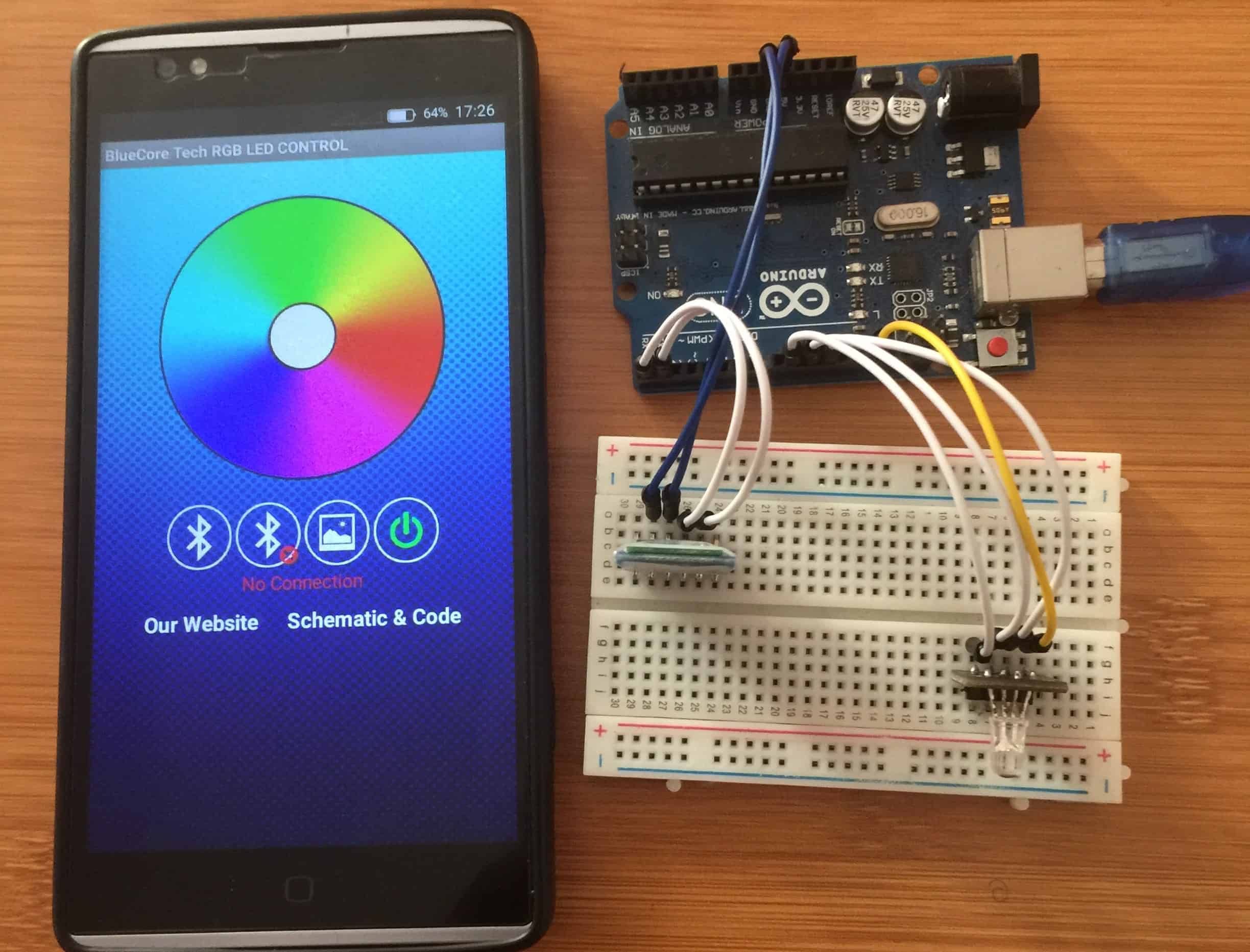
Android App used for Arduino RGB led Bluetooth control
For this project we use Arduino RGB Led Control app which is got from the Google play store. This Application enables us to connect the phone and the Arduino board through Bluetooth.
You can get the Application from here


