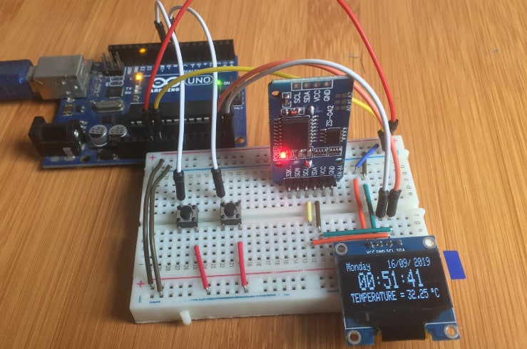
Real time clocks (RTCs) like DS3231 RTC are required in applications where we need to keep track of the current time for example in data logging, clock timers and alarms.
Most microcontrollers, including the Arduino, have a built-in timer that can keep track of longer time periods like minutes or days. However, this timer only keeps track of time since the microcontroller was last powered which means that whenever the power is turned off, the timer is set back to zero!
Real time Clocks on the other hand are simply watches that keep track of date and time even when the power supply to the microcontroller is turned off because they have power backups. In this tutorial I will look at how DS3231 RTC module works and how to interface it with Arduino for keeping time.
You can also read about the DS1307 RTC, another common Real Time Clock that I have covered in another tutorial from the link below.
DS3231 RTC Hardware Overview.
The DS3231 RTC module comes with I/O pins on either side. These pins configuration is similar and you can use whichever side you prefer depending on the application.
The pinout of the DS3231RTC RTC is as follows;
SCL – Serial clock input for the I2C interface
SDA – Serial data input/output for the I2C serial interface.
VCC – 3.3V to 5V power supply for the module.
GND – Ground pin.
BAT – Backup 3V power supply for keeping track of time when the main power supply is turned off.
SQW – For outputting square-wave frequencies of 1Hz, 4kHz, 8kHz or 32kHz.
32K – Outputs a stable, temperature compensated and accurate reference clock.
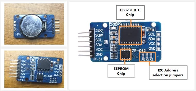
The major coponent of this RTC module is the DS3231 chip which is a low-cost and extremely accurate RTC chip. It is responsible for all timekeeping functions and can easily be interfaced with any microcontroller via the I2C protocol.
The DS3231 RTC is driven by a 32kHz Temperature Compensated Crystal Oscillator (TCXO) which is packaged inside the chip. This Crystal Oscillator is highly immune to the external temperature changes that often affect oscillation frequency and this is the reason why the module is more accurate at time keeping than other RTC modules.
Right next to the integrated crystal is a temperature sensor which compensates the frequency changes by adding or removing clock ticks so that the timekeeping stays on track.
The on board 32 bytes 24C32 EEPROM chip can be used to save settings or really anything. The 24C32 EEPROM uses I2C interface for communication and shares the same I2C bus as DS3231. The I2C address of the EEPROM can be changed easily with the three A0, A1 and A2 solder jumpers at the back. Each one of these is used to hardcode in the address. If a jumper is shorted with solder, that sets the address.
There is a battery backup at bottom side of the board that holds a 20mm 3V lithium coin cell (any CR2032 battery can fit well) for maintaining accurate timekeeping when main power to the device is interrupted. So you don’t need to worry about power outages, your MCU can still keep track of time.
Connecting the DS3231 RTC to Arduino
The DS3231 RTC uses I2C communication and will be connected to the Arduino Uno board as shown below.
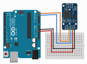
SCL to Pin A5
SDA to Pin A4
GND to Arduino ground
VCC to Arduino 5V.
Setting time of the DS3231 RTC
Before using the DS3231 rtc module, we need to first update it’s time and date settings. This is done by connecting the RTC module to an Arduino board and using already made libraries, we can be able to see the set time and date on the serial monitor.
The RTClib.h library is easy to use because it will automatically set the current date and time using the time on your computer. In case you need further reference on how to install the RTClib.h library from the Arduino IDE Library Manager you can check the link below where I describe in detail how this is done.
Code for setting the Time and Date for the DS3231 RTC using Arduino.
To set the time of the RTC, you can use the ds1307 example from RTClib library.
Go to File>Examples> RTClib> ds1307
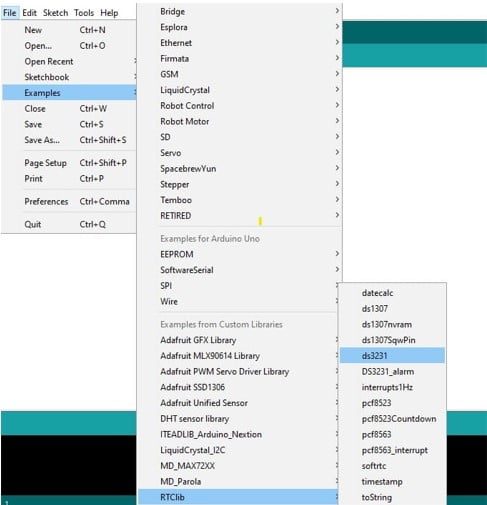
This will open the code below for displaying time and date on the Serial monitor .
#include "RTClib.h"
RTC_DS3231 rtc;
char daysOfTheWeek[7][12] = {"Sunday", "Monday", "Tuesday", "Wednesday", "Thursday", "Friday", "Saturday"};

void setup () {
#ifndef ESP8266
  while (!Serial); // for Leonardo/Micro/Zero
#endif
Serial.begin(9600);
delay(3000); // wait for console opening

  if (! rtc.begin()) {
    Serial.println("Couldn't find RTC");
    while (1);
  }

  if (rtc.lostPower()) {
Serial.println("RTC lost power, lets set the time!");
    // following line sets the RTC to the date & time this sketch was compiled
    rtc.adjust(DateTime(F(__DATE__), F(__TIME__)));
    // This line sets the RTC with an explicit date & time, for example to set
    // January 21, 2014 at 3am you would call:
    // rtc.adjust(DateTime(2014, 1, 21, 3, 0, 0));
  }
}

void loop () {
    DateTime now = rtc.now();

    Serial.print(now.year(), DEC);
    Serial.print('/');
    Serial.print(now.month(), DEC);
    Serial.print('/');
    Serial.print(now.day(), DEC);
    Serial.print(" (");
 Serial.print(daysOfTheWeek[now.dayOfTheWeek()]);
    Serial.print(") ");
    Serial.print(now.hour(), DEC);
    Serial.print(':');
    Serial.print(now.minute(), DEC);
    Serial.print(':');
    Serial.print(now.second(), DEC);
    Serial.println();

    Serial.print(" since midnight 1/1/1970 = ");
    Serial.print(now.unixtime());
    Serial.print("s = ");
    Serial.print(now.unixtime() / 86400L);
    Serial.println("d");

    // calculate a date which is 7 days and 30 seconds into the future
    DateTime future (now + TimeSpan(7,12,30,6));

    Serial.print(" now + 7d + 30s: ");
    Serial.print(future.year(), DEC);
 Serial.print('/');
    Serial.print(future.month(), DEC);
    Serial.print('/');
    Serial.print(future.day(), DEC);
    Serial.print(' ');
    Serial.print(future.hour(), DEC);
    Serial.print(':');
    Serial.print(future.minute(), DEC);
    Serial.print(':');
    Serial.print(future.second(), DEC);
    Serial.println();

    Serial.print("Temperature: ");
    Serial.print(rtc.getTemperature());
    Serial.println(" C");

    Serial.println();
    delay(3000);
}
Code Explanation
The Wire.h library is needed for I2C communication and the RTClib.h library contains the classes and methods that enable us to read data from the RTC module.
Then an object rtc is created from the RTC_DS3231 class which is part of the RTClib library. Also a 2D character array for storing the days of the week is defined.
In the setup section, we initialize the RTC module using the begin() method and the lostPower() method reads the DS3231 RTC’s internal I2C registers to check if the chip has lost track of time. If the function returns true, we can then set the date and time.
The adjust() function is for setting the date and time. This is an overloaded function.
In order to set the date and time of the RTC to correspond to the time at which the code sketch was compiled, we use the statement below.
rtc.adjust(DateTime(F(__DATE__), F(__TIME__)));
The date and date set using the above method will correspond to that on your computer.
To be able to set a specific date and time you can use;
rtc.adjust(DateTime(YYYY, M, D, H, M, s));
For example to set January 28 2020 at 12:56 this would be rtc.adjust(DateTime(2020, 1, 28, 12, 56, 0));
Note: After setting the desired time these statements should be commented out of the code sketch to avoid repetitive resetting of the time and date whenever you want to upload anew program
The loop section contains a number of methods from the DateTime class including;
- now() method returns current date and time.
- year() , month() and day() functions return the current year, month and day respectively.
- dayOfTheWeek() function returns current day of the week.
- hour(),minute() and second() functions return current hour, minutes and seconds respectively
- unixtime() function returns unix time in seconds.
- TimeSpan() function is used to add or subtract time to or from the current time. For example now() + TimeSpan(seconds) returns the future time with seconds added into current time.
When this code is uploaded to the Arduino, you will be able to observe the date and time that has been set.
The time and date can also be set manually using the code below. In this case we need to change the setup part of the code where the time and date are set from this line of code below.parse_cmd("T300608330032016",16);// this means 08:06:30 30.03.2016
//TssmmhhWDDMMYYYY(sec min hr day date month year)
After setting the time for the first time, the RTC stores the time and as such this line of code should be commented out for all other uses.
#include "ds3231.h"
#include "rtc_ds3231.h"

#define BUFF_MAX 128

uint8_t time[8];
char recv[BUFF_MAX];
unsigned int recv_size = 0;
unsigned long prev, interval = 5000;

void setup()
{
    Serial.begin(9600);
    DS3231_init(DS3231_CONTROL_INTCN);
    memset(recv, 0, BUFF_MAX);
    Serial.println("GET time");

    Serial.println("Setting time");
    //parse_cmd("T303515617082019",16); //Displayed
as 2019.08.17 15:35:34
    //           TssmmhhWDDMMYYYY

}

void loop()
{
    char in;
    char buff[BUFF_MAX];
    unsigned long now = millis();
    struct ts t;

    // show time once in a while
    if ((now - prev > interval) && (Serial.available() <= 0)) {
        DS3231_get(&t);

        // there is a compile time option in the library to include unixtime support
#ifdef CONFIG_UNIXTIME
        snprintf(buff,
BUFF_MAX, "%d.%02d.%02d %02d:%02d:%02d %ld", t.year,
             t.mon, t.mday, t.hour, t.min, t.sec, t.unixtime);
#else
        snprintf(buff, BUFF_MAX, "%d.%02d.%02d %02d:%02d:%02d", t.year,
             t.mon, t.mday, t.hour, t.min, t.sec);
#endif

        Serial.println(buff);
        prev = now;
    }

    if (Serial.available() > 0) {
        in = Serial.read();

        if ((in == 10 || in == 13) && (recv_size > 0)) {
            parse_cmd(recv, recv_size);
            recv_size = 0;
 recv[0] = 0;
        } else if (in < 48 || in > 122) {;       // ignore ~[0-9A-Za-z]
        } else if (recv_size > BUFF_MAX - 2) {   // drop lines that are too long
            // drop
            recv_size = 0;
            recv[0] = 0;
        } else if (recv_size < BUFF_MAX - 2) {
            recv[recv_size] = in;
            recv[recv_size + 1] = 0;
            recv_size += 1;
        }

    }
}

void parse_cmd(char *cmd, int cmdsize)
{
    uint8_t i;
    uint8_t reg_val;
 char buff[BUFF_MAX];
    struct ts t;

    //snprintf(buff, BUFF_MAX, "cmd was '%s' %d\n", cmd, cmdsize);
    //Serial.print(buff);

    // TssmmhhWDDMMYYYY aka set time
    if (cmd[0] == 84 && cmdsize == 16) {
        //T355720619112011
        t.sec = inp2toi(cmd, 1);
        t.min = inp2toi(cmd, 3);
        t.hour = inp2toi(cmd, 5);
        t.wday = cmd[7] - 48;
        t.mday = inp2toi(cmd, 8);
        t.mon = inp2toi(cmd, 10);
        t.year = inp2toi(cmd, 12) * 100 + inp2toi(cmd, 14);
        DS3231_set(t);
        Serial.println("OK");
    } else if (cmd[0] == 49 && cmdsize == 1) {
// "1" get alarm 1
        DS3231_get_a1(&buff[0], 59);
        Serial.println(buff);
    } else if (cmd[0] == 50 && cmdsize == 1) {  // "2" get alarm 1
        DS3231_get_a2(&buff[0], 59);
        Serial.println(buff);
    } else if (cmd[0] == 51 && cmdsize == 1) {  // "3" get aging register
        Serial.print("aging reg is ");
        Serial.println(DS3231_get_aging(), DEC);
    } else if (cmd[0] == 65 && cmdsize == 9) {  // "A" set alarm 1
        DS3231_set_creg(DS3231_CONTROL_INTCN | DS3231_CONTROL_A1IE);
        //ASSMMHHDD
        for (i = 0; i < 4; i++) {
time[i] = (cmd[2 * i + 1] - 48) * 10 + cmd[2 * i + 2] - 48; // ss, mm, hh, dd
        }
        uint8_t flags[5] = { 0, 0, 0, 0, 0 };
        DS3231_set_a1(time[0], time[1], time[2], time[3], flags);
        DS3231_get_a1(&buff[0], 59);
        Serial.println(buff);
    } else if (cmd[0] == 66 && cmdsize == 7) {  // "B" Set Alarm 2
        DS3231_set_creg(DS3231_CONTROL_INTCN | DS3231_CONTROL_A2IE);
        //BMMHHDD
        for (i = 0; i < 4; i++) {
            time[i] = (cmd[2 * i + 1] - 48) * 10
+ cmd[2 * i + 2] - 48; // mm, hh, dd
        }
        uint8_t flags[5] = { 0, 0, 0, 0 };
        DS3231_set_a2(time[0], time[1], time[2], flags);
        DS3231_get_a2(&buff[0], 59);
        Serial.println(buff);
    } else if (cmd[0] == 67 && cmdsize == 1) {  // "C" - get temperature register
        Serial.print("temperature reg is ");
        Serial.println(DS3231_get_treg(), DEC);
    } else if (cmd[0] == 68 && cmdsize == 1) {  // "D" - reset status register alarm flags
        reg_val = DS3231_get_sreg();
 reg_val &= B11111100;
        DS3231_set_sreg(reg_val);
    } else if (cmd[0] == 70 && cmdsize == 1) {  // "F" - custom fct
        reg_val = DS3231_get_addr(0x5);
        Serial.print("orig ");
        Serial.print(reg_val,DEC);
        Serial.print("month is ");
        Serial.println(bcdtodec(reg_val & 0x1F),DEC);
    } else if (cmd[0] == 71 && cmdsize == 1) {  // "G" - set aging status register
        DS3231_set_aging(0);
    } else if (cmd[0] == 83 && cmdsize == 1) {  // "S" - get status register
        Serial.print("status reg is ");
 Serial.println(DS3231_get_sreg(), DEC);
    } else {
        Serial.print("unknown command prefix ");
        Serial.println(cmd[0]);
        Serial.println(cmd[0], DEC);
    }
}
Displaying Time and Date of DS3231 RTC on 16×2 LCD.
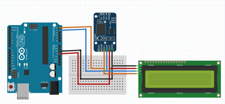
I’ll now show you how time, date and temperature reading from the D3231 RTC module connected to Arduino can be displayed on a 16×2 I2C LCD.
Since both the RTC and LCD are using I2C communication then the clock (SCL) and data (SDA) lines of both modules will be connected to Arduino analog pins A5 and A4 respectively as shown below.
Code for displaying the time and date on LCD.
#include <Wire.h>
#include "ds3231.h"
#include <LiquidCrystal_I2C.h>

//I2C pins declaration
LiquidCrystal_I2C lcd(0x27, 2, 1, 0, 4, 5, 6, 7, 3, POSITIVE);

#define BUFF_MAX 128

uint8_t time[8];
char recv[BUFF_MAX];
unsigned int recv_size = 0;
unsigned long prev, interval = 1000;

void setup()
{
    Serial.begin(9600);
    Wire.begin();
    DS3231_init(DS3231_CONTROL_INTCN);
    memset(recv, 0, BUFF_MAX);
    Serial.println("GET
time");
    lcd.begin(20, 4);
    lcd.backlight();//To Power ON the back light
    lcd.clear();

    //Serial.println("Setting time");
    //parse_cmd("T300608330032016",16);
  //           TssmmhhWDDMMYYYY
}

void loop()
{
    char in;
    char tempF[6];
    float temperature;
    char buff[BUFF_MAX];
    unsigned long now = millis();
    struct ts t;

    // show time once in a while
    if ((now - prev > interval) && (Serial.available() <= 0)) {
        DS3231_get(&t); //Get time
parse_cmd("C",1);
        temperature = DS3231_get_treg(); //Get temperature
        dtostrf(temperature, 5, 1, tempF);

        lcd.clear();
        lcd.setCursor(1,0);

        lcd.print(t.mday);

        printMonth(t.mon);

        lcd.print(t.year);

        lcd.setCursor(0,1); //Go to second line of the LCD Screen
        lcd.print(t.hour);
        lcd.print(":");
        if(t.min<10)
        {
          lcd.print("0");
        }
        lcd.print(t.min);
        lcd.print(":");
        if(t.sec<10)
        {
          lcd.print("0");
        }
        lcd.print(t.sec);
 lcd.print(' ');
        lcd.print(tempF);
        lcd.print((char)223);
        lcd.print("C ");
        prev = now;
    }


    if (Serial.available() > 0) {
        in = Serial.read();

        if ((in == 10 || in == 13) && (recv_size > 0)) {
            parse_cmd(recv, recv_size);
            recv_size = 0;
            recv[0] = 0;
        } else if (in < 48 || in > 122) {;       // ignore ~[0-9A-Za-z]
        } else if (recv_size > BUFF_MAX - 2) {   // drop lines that are too long
            // drop
            recv_size = 0;
 recv[0] = 0;
        } else if (recv_size < BUFF_MAX - 2) {
            recv[recv_size] = in;
            recv[recv_size + 1] = 0;
            recv_size += 1;
        }

    }
}

void parse_cmd(char *cmd, int cmdsize)
{
    uint8_t i;
    uint8_t reg_val;
    char buff[BUFF_MAX];
    struct ts t;

    //snprintf(buff, BUFF_MAX, "cmd was '%s' %d\n", cmd, cmdsize);
    //Serial.print(buff);

    // TssmmhhWDDMMYYYY aka set time
    if (cmd[0] == 84 && cmdsize == 16) {
        //T355720619112011
 t.sec = inp2toi(cmd, 1);
        t.min = inp2toi(cmd, 3);
        t.hour = inp2toi(cmd, 5);
        t.wday = inp2toi(cmd, 7);
        t.mday = inp2toi(cmd, 8);
        t.mon = inp2toi(cmd, 10);
        t.year = inp2toi(cmd, 12) * 100 + inp2toi(cmd, 14);
        DS3231_set(t);
        Serial.println("OK");
    } else if (cmd[0] == 49 && cmdsize == 1) {  // "1" get alarm 1
        DS3231_get_a1(&buff[0], 59);
        Serial.println(buff);
    } else if (cmd[0] == 50 && cmdsize == 1) {  // "2" get alarm 1
        DS3231_get_a2(&buff[0], 59);
        Serial.println(buff);
 } else if (cmd[0] == 51 && cmdsize == 1) {  // "3" get aging register
        Serial.print("aging reg is ");
        Serial.println(DS3231_get_aging(), DEC);
    } else if (cmd[0] == 65 && cmdsize == 9) {  // "A" set alarm 1
        DS3231_set_creg(DS3231_CONTROL_INTCN | DS3231_CONTROL_A1IE);
        //ASSMMHHDD
        for (i = 0; i < 4; i++) {
            time[i] = (cmd[2 * i + 1] - 48) * 10 + cmd[2 * i + 2] - 48; // ss, mm, hh, dd
        }
        byte flags[5] = { 0, 0, 0, 0, 0 };
        DS3231_set_a1(time[0], time[1], time[2],
time[3], flags);
        DS3231_get_a1(&buff[0], 59);
        Serial.println(buff);
    } else if (cmd[0] == 66 && cmdsize == 7) {  // "B" Set Alarm 2
        DS3231_set_creg(DS3231_CONTROL_INTCN | DS3231_CONTROL_A2IE);
        //BMMHHDD
        for (i = 0; i < 4; i++) {
            time[i] = (cmd[2 * i + 1] - 48) * 10 + cmd[2 * i + 2] - 48; // mm, hh, dd
        }
        byte flags[5] = { 0, 0, 0, 0 };
        DS3231_set_a2(time[0], time[1], time[2], flags);
        DS3231_get_a2(&buff[0], 59);
Serial.println(buff);
    } else if (cmd[0] == 67 && cmdsize == 1) {  // "C" - get temperature register
        Serial.print("temperature reg is ");
        Serial.println(DS3231_get_treg(), DEC);
    } else if (cmd[0] == 68 && cmdsize == 1) {  // "D" - reset status register alarm flags
        reg_val = DS3231_get_sreg();
        reg_val &= B11111100;
        DS3231_set_sreg(reg_val);
    } else if (cmd[0] == 70 && cmdsize == 1) {  // "F" - custom fct
        reg_val = DS3231_get_addr(0x5);
        Serial.print("orig ");
        Serial.print(reg_val,DEC);
        Serial.prin
("month is ");
        Serial.println(bcdtodec(reg_val & 0x1F),DEC);
    } else if (cmd[0] == 71 && cmdsize == 1) {  // "G" - set aging status register
        DS3231_set_aging(0);
    } else if (cmd[0] == 83 && cmdsize == 1) {  // "S" - get status register
        Serial.print("status reg is ");
        Serial.println(DS3231_get_sreg(), DEC);
    } else {
        Serial.print("unknown command prefix ");
        Serial.println(cmd[0]);
        Serial.println(cmd[0], DEC);
    }
}
void printMonth(int month)
{
  switch(month)
  {
    case 1: lcd.print(" January ");break;
    case 2: lcd.print(" February ");break;
    case 3: lcd.print(" March ");break;
    case 4: lcd.print(" April ");break;
    case 5: lcd.print(" May ");break;
    case 6: lcd.print(" June ");break;
    case 7: lcd.print(" July ");break;
    case 8: lcd.print(" August ");break;
    case 9: lcd.print(" September ");break;
    case 10: lcd.print(" October ");break;
    case 11: lcd.print(" November ");break;
    case 12: lcd.print(" December ");break;
    default: lcd.print(" Error ");break;
  }
}
Digital clock using DS3231RTC with Arduino and I2C OLED display.
Finally, I’ll demonstrate how the DS3231 RTC module can be used to make a simple digital clock using Arduino and SSD1306 OLED. Before proceeding you should know how to interface the OLED with Arduino.
You can make reference from my other tutorial on how to use the SSD1306 OLED with Arduino using the link below.
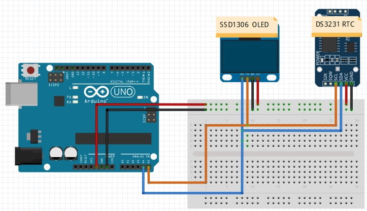
The first setup for the DS3231 OLED clock we shall just simply connect the OLED and the RTC to Arduino so that we can display time and temperature.
The schematic of the setup is as shown below. Since both the SSD1306 OLED and the DS3231 RTC are I2C devices we just connect the corresponding pins as;
- SCL to Arduino analog pin A5
- SDA to Arduino analog pin A4
- GND to Arduino GROUND
- VCC to Arduino 5V
Code for Digital clock using DS3231 RTC and OLED Display.
The code is almost the same as was used in the previous tutorials only that this time we add the part for the OLED. In this case the date, time and temperature will be automatically updated and displayed on the OLED.
#include <SPI.h>
#include <Wire.h>
#include <Adafruit_GFX.h>
#include <Adafruit_SSD1306.h>
#include "RTClib.h"
RTC_DS3231 rtc;
char daysOfTheWeek[7][12] = {"Sunday", "Monday", "Tuesday", "Wednesday", "Thursday", "Friday", "Saturday"};
#define SCREEN_WIDTH 128 // OLED display width, in pixels
#define SCREEN_HEIGHT 32 // OLED display height, in pixels
#define OLED_RESET 4
Adafruit_SSD1306 display(SCREEN_WIDTH, SCREEN_HEIGHT, &Wire, OLED_RESET);
void setup() {
  Serial.begin(9600);
  delay(3000); // wait for console opening
  if (! rtc.begin()) {
    Serial.println("Couldn't find RTC");
    while (1);
  }
  if (rtc.lostPower()) {
    Serial.println("RTC lost power, lets set the time!");
    // following line sets the RTC to the date & time this sketch was compiled
    rtc.adjust(DateTime(F(__DATE__), F(__TIME__)));
    // This line sets the RTC with an explicit date & time, for example to set
    // January 21, 2014 at 3am you would call:
    // rtc.adjust(DateTime(2014, 1, 21, 3, 0, 0));
  }
  display.begin(SSD1306_SWITCHCAPVCC, 0x3C);  // initialize with the I2C addr 0x3C (for the 128x32)// Check your I2C address and enter it here, in Our case address is 0x3C
  display.clearDisplay();
  display.display(); // this command will display all the data which is in buffer
  display.setTextColor(WHITE, BLACK);
  display.drawRect(117, 25, 3, 3, WHITE);     // Put degree symbol ( ° )
  draw_text(0, 25, "TEMPERATURE =", 1);
  draw_text(122, 25, "C", 1);
}
void loop() {
  DateTime now = rtc.now();
  /*============Display Date=================*/
display.setTextSize(1);
display.setCursor(0,0);
display.print(daysOfTheWeek[now.dayOfTheWeek()]);
char currentDate [16];
uint8_t thisDay, thisMonth ;
thisDay = now.day();
thisMonth = now.month();
sprintf (currentDate, "%02d/%02d/", thisDay, thisMonth); //add leading zeros to the day and month
display.setTextSize(1);
display.setCursor(62,0);
display.print(currentDate);
display.setTextSize(1);
display.setCursor(102,0);
display.print(now.year(), DEC);
/*================Display Time================*/
char buffer [16];
uint8_t thisSec, thisMin, thisHour;
thisSec = now.second();
thisMin = now.minute();
thisHour = now.hour();
sprintf (buffer, "%02d:%02d:%02d", thisHour, thisMin, thisSec);
display.setTextSize(2);
display.setCursor(15,9);
display.print(buffer);
/*=============Display Temperature=====================*/
display.setTextSize(1);
display.setCursor(82,25);
display.print(rtc.getTemperature());
display.display();
}
void draw_text(byte x_pos, byte y_pos, char *text, byte text_size) {
  display.setCursor(x_pos, y_pos);
  display.setTextSize(text_size);
  display.print(text);
  display.display();
}
#include <SPI.h>
#include <Wire.h>                        // Include Wire library (required for I2C devices)
#include <Adafruit_GFX.h>                // Include Adafruit graphics library
#include <Adafruit_SSD1306.h>            // Include Adafruit SSD1306 OLED driver
#define SCREEN_WIDTH 128 // OLED display width, in pixels
#define SCREEN_HEIGHT 32 // OLED display height, in pixels

#define OLED_RESET 4
Adafruit_SSD1306 display(SCREEN_WIDTH, SCREEN_HEIGHT, &Wire, OLED_RESET);

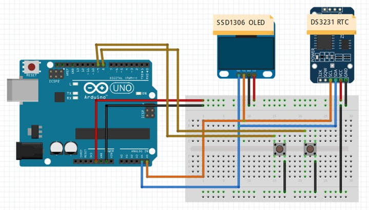
#define button1    9                       // Button B1 is connected to Arduino pin 9
#define button2    8                       // Button B2 is connected to Arduino pin 8

void setup(void) {
  pinMode(button1, INPUT_PULLUP);
  pinMode(button2, INPUT_PULLUP);
  delay(1000);

  // by default, we'll generate the high voltage from the 3.3v line internally! (neat!)
  display.begin(SSD1306_SWITCHCAPVCC, 0x3C);  // initialize with the I2C addr
  // init done

  // Clear the display buffer.
  display.clearDisplay();
  display.display();

  display.setTextColor(WHITE, BLACK);
  display.drawRect(117, 25, 3, 3, WHITE);     // Put degree symbol ( ° )
  draw_text(0, 25, "TEMPERATURE =", 1);
  draw_text(122, 25, "C", 1);
}

char Time[]     = "  :  :  ";
char Calendar[] = "  /  /20  ";
char temperature[] = " 00.00";
char temperature_msb;
byte i, second, minute, hour, day, date, month, year, temperature_lsb;

void display_day(){
  switch(day){
    case 1:  draw_text(0, 0, " SUNDAY  ", 1); break;
    case 2:  draw_text(0, 0, " MONDAY  ", 1); break;
    case 3:  draw_text(0, 0, " TUESDAY ", 1); break;
    case 4:  draw_text(0, 0, "WEDNESDAY", 1); break;
    case 5:  draw_text(0, 0, "THURSDAY ", 1); break;
    case 6:  draw_text(0, 0, " FRIDAY  ", 1); break;
    default: draw_text(0, 0, "SATURDAY ", 1);
  }
}

void DS3231_display(){
  // Convert BCD to decimal
  second = (second >> 4) * 10 + (second & 0x0F);
  minute = (minute >> 4) * 10 + (minute & 0x0F);
  hour   = (hour >> 4)   * 10 + (hour & 0x0F);
  date   = (date >> 4)   * 10 + (date & 0x0F);
  month  = (month >> 4)  * 10 + (month & 0x0F);
  year   = (year >> 4)   * 10 + (year & 0x0F);
  // End conversion

  Time[7]     = second % 10 + 48;
  Time[6]     = second / 10 + 48;
  Time[4]     = minute % 10 + 48;
  Time[3]     = minute / 10 + 48;
  Time[1]     = hour   % 10 + 48;
  Time[0]     = hour   / 10 + 48;
  Calendar[9] = year   % 10 + 48;
  Calendar[8] = year   / 10 + 48;
  Calendar[4] = month  % 10 + 48;
  Calendar[3] = month  / 10 + 48;
  Calendar[1] = date   % 10 + 48;
  Calendar[0] = date   / 10 + 48;
  if(temperature_msb < 0){
    temperature_msb = abs(temperature_msb);
    temperature[0] = '-';
  }
  else
    temperature[0] = ' ';
  temperature_lsb >>= 6;
  temperature[2] = temperature_msb % 10  + 48;
  temperature[1] = temperature_msb / 10  + 48;
  if(temperature_lsb == 0 || temperature_lsb == 2){
    temperature[5] = '0';
    if(temperature_lsb == 0) temperature[4] = '0';
    else                     temperature[4] = '5';
  }
  if(temperature_lsb == 1 || temperature_lsb == 3){
    temperature[5] = '5';
    if(temperature_lsb == 1) temperature[4] = '2';
    else                     temperature[4] = '7';
  }

  draw_text(60,  0, Calendar, 1);                     // Display the date (format: dd/mm/yyyy)
  draw_text(10, 9, Time, 2);                         // Display the time
  draw_text(75, 25, temperature, 1);                  // Display the temperature
}

void blink_parameter(){
  byte j = 0;
  while(j < 10 && digitalRead(button1) && digitalRead(button2)){
    j++;
    delay(25);
  }
}

byte edit(byte x_pos, byte y_pos, byte parameter){
  char text[3];
  sprintf(text,"%02u", parameter);
  while(!digitalRead(button1));                      // Wait until button B1 released
  while(true){
    while(!digitalRead(button2)){                    // If button B2 is pressed
      parameter++;
      if(i == 0 && parameter > 31)                   // If date > 31 ==> date = 1
        parameter = 1;
      if(i == 1 && parameter > 12)                   // If month > 12 ==> month = 1
        parameter = 1;
      if(i == 2 && parameter > 99)                   // If year > 99 ==> year = 0
        parameter = 0;
      if(i == 3 && parameter > 23)                   // If hours > 23 ==> hours = 0
        parameter = 0;
      if(i == 4 && parameter > 59)                   // If minutes > 59 ==> minutes = 0
        parameter = 0;
      sprintf(text,"%02u", parameter);
      draw_text(x_pos, y_pos, text, 1);
      delay(200);                                    // Wait 200ms
    }
    draw_text(x_pos, y_pos, "  ", 1);
    blink_parameter();
    draw_text(x_pos, y_pos, text, 1);
    blink_parameter();
    if(!digitalRead(button1)){                       // If button B1 is pressed
      i++;                                           // Increament 'i' for the next parameter
      return parameter;                              // Return parameter value and exit
    }
  }
}

void draw_text(byte x_pos, byte y_pos, char *text, byte text_size) {
  display.setCursor(x_pos, y_pos);
  display.setTextSize(text_size);
  display.print(text);
  display.display();
}

void loop() {

  if(!digitalRead(button1)){                         // If button B1 is pressed
    i = 0;
    while(!digitalRead(button1));                    // Wait for button B1 release
    while(true){
      while(!digitalRead(button2)){                  // While button B2 pressed
        day++;                                       // Increment day
        if(day > 7) day = 1;
        display_day();                               // Call display_day function
        delay(200);                                  // Wait 200 ms
      }
      draw_text(0, 0, "         ", 1);
      blink_parameter();                             // Call blink_parameter function
      display_day();                                 // Call display_day function
      blink_parameter();                             // Call blink_parameter function
      if(!digitalRead(button1))                      // If button B1 is pressed
        break;
    }
    //set position of text when editing on button press
    date   = edit(60, 0, date);                      // Edit date
    month  = edit(80, 0, month);                    // Edit month
    year   = edit(110,0, year);                    // Edit year
    hour   = edit(14, 9, hour);                     // Edit hours
    minute = edit(50, 9, minute);                   // Edit minutes

    // Convert decimal to BCD
    minute = ((minute / 10) << 4) + (minute % 10);
    hour = ((hour / 10) << 4) + (hour % 10);
    date = ((date / 10) << 4) + (date % 10);
    month = ((month / 10) << 4) + (month % 10);
    year = ((year / 10) << 4) + (year % 10);
    // End conversion

    // Write data to DS3231 RTC
    Wire.beginTransmission(0x68);               // Start I2C protocol with DS3231 address
    Wire.write(0);                              // Send register address
    Wire.write(0);                              // Reset sesonds and start oscillator
    Wire.write(minute);                         // Write minute
    Wire.write(hour);                           // Write hour
    Wire.write(day);                            // Write day
    Wire.write(date);                           // Write date
    Wire.write(month);                          // Write month
    Wire.write(year);                           // Write year
    Wire.endTransmission();                     // Stop transmission and release the I2C bus
    delay(200);                                 // Wait 200ms
  }

  Wire.beginTransmission(0x68);                 // Start I2C protocol with DS3231 address
  Wire.write(0);                                // Send register address
  Wire.endTransmission(false);                  // I2C restart
  Wire.requestFrom(0x68, 7);                    // Request 7 bytes from DS3231 and release I2C bus at end of reading
  second = Wire.read();                         // Read seconds from register 0
  minute = Wire.read();                         // Read minuts from register 1
  hour   = Wire.read();                         // Read hour from register 2
  day    = Wire.read();                         // Read day from register 3
  date   = Wire.read();                         // Read date from register 4
  month  = Wire.read();                         // Read month from register 5
  year   = Wire.read();                         // Read year from register 6
  Wire.beginTransmission(0x68);                 // Start I2C protocol with DS3231 address
  Wire.write(0x11);                             // Send register address
  Wire.endTransmission(false);                  // I2C restart
  Wire.requestFrom(0x68, 2);                    // Request 2 bytes from DS3231 and release I2C bus at end of reading
  temperature_msb = Wire.read();                // Read temperature MSB
  temperature_lsb = Wire.read();                // Read temperature LSB

  display_day();
  DS3231_display();                             // Diaplay time & calendar

  delay(50);                                    // Wait 50ms
}
When this code is uploaded to the Arduino board, you can use the buttons to set the time and date which will be stored by the RTC and can keep accurately this set time even when the power supply to the microcontroller is turned off. The OLED will display the set time, date and temperature.
